CN102933178A - Medical device lock mechanism - Google Patents
Medical device lock mechanism Download PDFInfo
- Publication number
- CN102933178A CN102933178A CN2011800190744A CN201180019074A CN102933178A CN 102933178 A CN102933178 A CN 102933178A CN 2011800190744 A CN2011800190744 A CN 2011800190744A CN 201180019074 A CN201180019074 A CN 201180019074A CN 102933178 A CN102933178 A CN 102933178A
- Authority
- CN
- China
- Prior art keywords
- sections
- implant
- locking member
- treatment device
- medical treatment
- Prior art date
- Legal status (The legal status is an assumption and is not a legal conclusion. Google has not performed a legal analysis and makes no representation as to the accuracy of the status listed.)
- Pending
Links
Images


Classifications
-
- A—HUMAN NECESSITIES
- A61—MEDICAL OR VETERINARY SCIENCE; HYGIENE
- A61F—FILTERS IMPLANTABLE INTO BLOOD VESSELS; PROSTHESES; DEVICES PROVIDING PATENCY TO, OR PREVENTING COLLAPSING OF, TUBULAR STRUCTURES OF THE BODY, e.g. STENTS; ORTHOPAEDIC, NURSING OR CONTRACEPTIVE DEVICES; FOMENTATION; TREATMENT OR PROTECTION OF EYES OR EARS; BANDAGES, DRESSINGS OR ABSORBENT PADS; FIRST-AID KITS
- A61F2/00—Filters implantable into blood vessels; Prostheses, i.e. artificial substitutes or replacements for parts of the body; Appliances for connecting them with the body; Devices providing patency to, or preventing collapsing of, tubular structures of the body, e.g. stents
- A61F2/02—Prostheses implantable into the body
- A61F2/30—Joints
- A61F2/44—Joints for the spine, e.g. vertebrae, spinal discs
-
- A—HUMAN NECESSITIES
- A61—MEDICAL OR VETERINARY SCIENCE; HYGIENE
- A61B—DIAGNOSIS; SURGERY; IDENTIFICATION
- A61B17/00—Surgical instruments, devices or methods, e.g. tourniquets
- A61B17/56—Surgical instruments or methods for treatment of bones or joints; Devices specially adapted therefor
- A61B17/58—Surgical instruments or methods for treatment of bones or joints; Devices specially adapted therefor for osteosynthesis, e.g. bone plates, screws, setting implements or the like
- A61B17/68—Internal fixation devices, including fasteners and spinal fixators, even if a part thereof projects from the skin
- A61B17/70—Spinal positioners or stabilisers ; Bone stabilisers comprising fluid filler in an implant
-
- A—HUMAN NECESSITIES
- A61—MEDICAL OR VETERINARY SCIENCE; HYGIENE
- A61F—FILTERS IMPLANTABLE INTO BLOOD VESSELS; PROSTHESES; DEVICES PROVIDING PATENCY TO, OR PREVENTING COLLAPSING OF, TUBULAR STRUCTURES OF THE BODY, e.g. STENTS; ORTHOPAEDIC, NURSING OR CONTRACEPTIVE DEVICES; FOMENTATION; TREATMENT OR PROTECTION OF EYES OR EARS; BANDAGES, DRESSINGS OR ABSORBENT PADS; FIRST-AID KITS
- A61F2/00—Filters implantable into blood vessels; Prostheses, i.e. artificial substitutes or replacements for parts of the body; Appliances for connecting them with the body; Devices providing patency to, or preventing collapsing of, tubular structures of the body, e.g. stents
- A61F2/02—Prostheses implantable into the body
- A61F2/28—Bones
-
- A—HUMAN NECESSITIES
- A61—MEDICAL OR VETERINARY SCIENCE; HYGIENE
- A61F—FILTERS IMPLANTABLE INTO BLOOD VESSELS; PROSTHESES; DEVICES PROVIDING PATENCY TO, OR PREVENTING COLLAPSING OF, TUBULAR STRUCTURES OF THE BODY, e.g. STENTS; ORTHOPAEDIC, NURSING OR CONTRACEPTIVE DEVICES; FOMENTATION; TREATMENT OR PROTECTION OF EYES OR EARS; BANDAGES, DRESSINGS OR ABSORBENT PADS; FIRST-AID KITS
- A61F2/00—Filters implantable into blood vessels; Prostheses, i.e. artificial substitutes or replacements for parts of the body; Appliances for connecting them with the body; Devices providing patency to, or preventing collapsing of, tubular structures of the body, e.g. stents
- A61F2/02—Prostheses implantable into the body
- A61F2/30—Joints
- A61F2/44—Joints for the spine, e.g. vertebrae, spinal discs
- A61F2/4455—Joints for the spine, e.g. vertebrae, spinal discs for the fusion of spinal bodies, e.g. intervertebral fusion of adjacent spinal bodies, e.g. fusion cages
-
- A—HUMAN NECESSITIES
- A61—MEDICAL OR VETERINARY SCIENCE; HYGIENE
- A61B—DIAGNOSIS; SURGERY; IDENTIFICATION
- A61B17/00—Surgical instruments, devices or methods, e.g. tourniquets
- A61B17/56—Surgical instruments or methods for treatment of bones or joints; Devices specially adapted therefor
- A61B17/58—Surgical instruments or methods for treatment of bones or joints; Devices specially adapted therefor for osteosynthesis, e.g. bone plates, screws, setting implements or the like
- A61B17/68—Internal fixation devices, including fasteners and spinal fixators, even if a part thereof projects from the skin
- A61B17/70—Spinal positioners or stabilisers ; Bone stabilisers comprising fluid filler in an implant
- A61B17/7094—Solid vertebral fillers; devices for inserting such fillers
-
- A—HUMAN NECESSITIES
- A61—MEDICAL OR VETERINARY SCIENCE; HYGIENE
- A61B—DIAGNOSIS; SURGERY; IDENTIFICATION
- A61B17/00—Surgical instruments, devices or methods, e.g. tourniquets
- A61B17/56—Surgical instruments or methods for treatment of bones or joints; Devices specially adapted therefor
- A61B17/58—Surgical instruments or methods for treatment of bones or joints; Devices specially adapted therefor for osteosynthesis, e.g. bone plates, screws, setting implements or the like
- A61B17/88—Osteosynthesis instruments; Methods or means for implanting or extracting internal or external fixation devices
- A61B17/885—Tools for expanding or compacting bones or discs or cavities therein
- A61B17/8852—Tools for expanding or compacting bones or discs or cavities therein capable of being assembled or enlarged, or changing shape, inside the bone or disc
-
- A—HUMAN NECESSITIES
- A61—MEDICAL OR VETERINARY SCIENCE; HYGIENE
- A61F—FILTERS IMPLANTABLE INTO BLOOD VESSELS; PROSTHESES; DEVICES PROVIDING PATENCY TO, OR PREVENTING COLLAPSING OF, TUBULAR STRUCTURES OF THE BODY, e.g. STENTS; ORTHOPAEDIC, NURSING OR CONTRACEPTIVE DEVICES; FOMENTATION; TREATMENT OR PROTECTION OF EYES OR EARS; BANDAGES, DRESSINGS OR ABSORBENT PADS; FIRST-AID KITS
- A61F2/00—Filters implantable into blood vessels; Prostheses, i.e. artificial substitutes or replacements for parts of the body; Appliances for connecting them with the body; Devices providing patency to, or preventing collapsing of, tubular structures of the body, e.g. stents
- A61F2/02—Prostheses implantable into the body
- A61F2/28—Bones
- A61F2002/2835—Bone graft implants for filling a bony defect or an endoprosthesis cavity, e.g. by synthetic material or biological material
-
- A—HUMAN NECESSITIES
- A61—MEDICAL OR VETERINARY SCIENCE; HYGIENE
- A61F—FILTERS IMPLANTABLE INTO BLOOD VESSELS; PROSTHESES; DEVICES PROVIDING PATENCY TO, OR PREVENTING COLLAPSING OF, TUBULAR STRUCTURES OF THE BODY, e.g. STENTS; ORTHOPAEDIC, NURSING OR CONTRACEPTIVE DEVICES; FOMENTATION; TREATMENT OR PROTECTION OF EYES OR EARS; BANDAGES, DRESSINGS OR ABSORBENT PADS; FIRST-AID KITS
- A61F2/00—Filters implantable into blood vessels; Prostheses, i.e. artificial substitutes or replacements for parts of the body; Appliances for connecting them with the body; Devices providing patency to, or preventing collapsing of, tubular structures of the body, e.g. stents
- A61F2/02—Prostheses implantable into the body
- A61F2/30—Joints
- A61F2002/30001—Additional features of subject-matter classified in A61F2/28, A61F2/30 and subgroups thereof
- A61F2002/30316—The prosthesis having different structural features at different locations within the same prosthesis; Connections between prosthetic parts; Special structural features of bone or joint prostheses not otherwise provided for
- A61F2002/30329—Connections or couplings between prosthetic parts, e.g. between modular parts; Connecting elements
- A61F2002/30331—Connections or couplings between prosthetic parts, e.g. between modular parts; Connecting elements made by longitudinally pushing a protrusion into a complementarily-shaped recess, e.g. held by friction fit
- A61F2002/30362—Connections or couplings between prosthetic parts, e.g. between modular parts; Connecting elements made by longitudinally pushing a protrusion into a complementarily-shaped recess, e.g. held by friction fit with possibility of relative movement between the protrusion and the recess
- A61F2002/30364—Rotation about the common longitudinal axis
- A61F2002/30367—Rotation about the common longitudinal axis with additional means for preventing said rotation
-
- A—HUMAN NECESSITIES
- A61—MEDICAL OR VETERINARY SCIENCE; HYGIENE
- A61F—FILTERS IMPLANTABLE INTO BLOOD VESSELS; PROSTHESES; DEVICES PROVIDING PATENCY TO, OR PREVENTING COLLAPSING OF, TUBULAR STRUCTURES OF THE BODY, e.g. STENTS; ORTHOPAEDIC, NURSING OR CONTRACEPTIVE DEVICES; FOMENTATION; TREATMENT OR PROTECTION OF EYES OR EARS; BANDAGES, DRESSINGS OR ABSORBENT PADS; FIRST-AID KITS
- A61F2/00—Filters implantable into blood vessels; Prostheses, i.e. artificial substitutes or replacements for parts of the body; Appliances for connecting them with the body; Devices providing patency to, or preventing collapsing of, tubular structures of the body, e.g. stents
- A61F2/02—Prostheses implantable into the body
- A61F2/30—Joints
- A61F2002/30001—Additional features of subject-matter classified in A61F2/28, A61F2/30 and subgroups thereof
- A61F2002/30316—The prosthesis having different structural features at different locations within the same prosthesis; Connections between prosthetic parts; Special structural features of bone or joint prostheses not otherwise provided for
- A61F2002/30329—Connections or couplings between prosthetic parts, e.g. between modular parts; Connecting elements
- A61F2002/30462—Connections or couplings between prosthetic parts, e.g. between modular parts; Connecting elements retained or tied with a rope, string, thread, wire or cable
-
- A—HUMAN NECESSITIES
- A61—MEDICAL OR VETERINARY SCIENCE; HYGIENE
- A61F—FILTERS IMPLANTABLE INTO BLOOD VESSELS; PROSTHESES; DEVICES PROVIDING PATENCY TO, OR PREVENTING COLLAPSING OF, TUBULAR STRUCTURES OF THE BODY, e.g. STENTS; ORTHOPAEDIC, NURSING OR CONTRACEPTIVE DEVICES; FOMENTATION; TREATMENT OR PROTECTION OF EYES OR EARS; BANDAGES, DRESSINGS OR ABSORBENT PADS; FIRST-AID KITS
- A61F2/00—Filters implantable into blood vessels; Prostheses, i.e. artificial substitutes or replacements for parts of the body; Appliances for connecting them with the body; Devices providing patency to, or preventing collapsing of, tubular structures of the body, e.g. stents
- A61F2/02—Prostheses implantable into the body
- A61F2/30—Joints
- A61F2002/30001—Additional features of subject-matter classified in A61F2/28, A61F2/30 and subgroups thereof
- A61F2002/30316—The prosthesis having different structural features at different locations within the same prosthesis; Connections between prosthetic parts; Special structural features of bone or joint prostheses not otherwise provided for
- A61F2002/30329—Connections or couplings between prosthetic parts, e.g. between modular parts; Connecting elements
- A61F2002/30469—Connections or couplings between prosthetic parts, e.g. between modular parts; Connecting elements using band clamps
-
- A—HUMAN NECESSITIES
- A61—MEDICAL OR VETERINARY SCIENCE; HYGIENE
- A61F—FILTERS IMPLANTABLE INTO BLOOD VESSELS; PROSTHESES; DEVICES PROVIDING PATENCY TO, OR PREVENTING COLLAPSING OF, TUBULAR STRUCTURES OF THE BODY, e.g. STENTS; ORTHOPAEDIC, NURSING OR CONTRACEPTIVE DEVICES; FOMENTATION; TREATMENT OR PROTECTION OF EYES OR EARS; BANDAGES, DRESSINGS OR ABSORBENT PADS; FIRST-AID KITS
- A61F2/00—Filters implantable into blood vessels; Prostheses, i.e. artificial substitutes or replacements for parts of the body; Appliances for connecting them with the body; Devices providing patency to, or preventing collapsing of, tubular structures of the body, e.g. stents
- A61F2/02—Prostheses implantable into the body
- A61F2/30—Joints
- A61F2002/30001—Additional features of subject-matter classified in A61F2/28, A61F2/30 and subgroups thereof
- A61F2002/30316—The prosthesis having different structural features at different locations within the same prosthesis; Connections between prosthetic parts; Special structural features of bone or joint prostheses not otherwise provided for
- A61F2002/30329—Connections or couplings between prosthetic parts, e.g. between modular parts; Connecting elements
- A61F2002/30518—Connections or couplings between prosthetic parts, e.g. between modular parts; Connecting elements with possibility of relative movement between the prosthetic parts
- A61F2002/3052—Connections or couplings between prosthetic parts, e.g. between modular parts; Connecting elements with possibility of relative movement between the prosthetic parts unrestrained in only one direction, e.g. moving unidirectionally
- A61F2002/30522—Connections or couplings between prosthetic parts, e.g. between modular parts; Connecting elements with possibility of relative movement between the prosthetic parts unrestrained in only one direction, e.g. moving unidirectionally releasable, e.g. using a releasable ratchet
-
- A—HUMAN NECESSITIES
- A61—MEDICAL OR VETERINARY SCIENCE; HYGIENE
- A61F—FILTERS IMPLANTABLE INTO BLOOD VESSELS; PROSTHESES; DEVICES PROVIDING PATENCY TO, OR PREVENTING COLLAPSING OF, TUBULAR STRUCTURES OF THE BODY, e.g. STENTS; ORTHOPAEDIC, NURSING OR CONTRACEPTIVE DEVICES; FOMENTATION; TREATMENT OR PROTECTION OF EYES OR EARS; BANDAGES, DRESSINGS OR ABSORBENT PADS; FIRST-AID KITS
- A61F2/00—Filters implantable into blood vessels; Prostheses, i.e. artificial substitutes or replacements for parts of the body; Appliances for connecting them with the body; Devices providing patency to, or preventing collapsing of, tubular structures of the body, e.g. stents
- A61F2/02—Prostheses implantable into the body
- A61F2/30—Joints
- A61F2002/30001—Additional features of subject-matter classified in A61F2/28, A61F2/30 and subgroups thereof
- A61F2002/30621—Features concerning the anatomical functioning or articulation of the prosthetic joint
- A61F2002/30624—Hinged joint, e.g. with transverse axle restricting the movement
- A61F2002/30632—Hinged joint, e.g. with transverse axle restricting the movement with rotation-limiting stops, e.g. projections or recesses
-
- A—HUMAN NECESSITIES
- A61—MEDICAL OR VETERINARY SCIENCE; HYGIENE
- A61F—FILTERS IMPLANTABLE INTO BLOOD VESSELS; PROSTHESES; DEVICES PROVIDING PATENCY TO, OR PREVENTING COLLAPSING OF, TUBULAR STRUCTURES OF THE BODY, e.g. STENTS; ORTHOPAEDIC, NURSING OR CONTRACEPTIVE DEVICES; FOMENTATION; TREATMENT OR PROTECTION OF EYES OR EARS; BANDAGES, DRESSINGS OR ABSORBENT PADS; FIRST-AID KITS
- A61F2/00—Filters implantable into blood vessels; Prostheses, i.e. artificial substitutes or replacements for parts of the body; Appliances for connecting them with the body; Devices providing patency to, or preventing collapsing of, tubular structures of the body, e.g. stents
- A61F2/02—Prostheses implantable into the body
- A61F2/30—Joints
- A61F2/44—Joints for the spine, e.g. vertebrae, spinal discs
- A61F2002/4415—Joints for the spine, e.g. vertebrae, spinal discs elements of the prosthesis being arranged in a chain like manner
-
- A—HUMAN NECESSITIES
- A61—MEDICAL OR VETERINARY SCIENCE; HYGIENE
- A61F—FILTERS IMPLANTABLE INTO BLOOD VESSELS; PROSTHESES; DEVICES PROVIDING PATENCY TO, OR PREVENTING COLLAPSING OF, TUBULAR STRUCTURES OF THE BODY, e.g. STENTS; ORTHOPAEDIC, NURSING OR CONTRACEPTIVE DEVICES; FOMENTATION; TREATMENT OR PROTECTION OF EYES OR EARS; BANDAGES, DRESSINGS OR ABSORBENT PADS; FIRST-AID KITS
- A61F2/00—Filters implantable into blood vessels; Prostheses, i.e. artificial substitutes or replacements for parts of the body; Appliances for connecting them with the body; Devices providing patency to, or preventing collapsing of, tubular structures of the body, e.g. stents
- A61F2/02—Prostheses implantable into the body
- A61F2/30—Joints
- A61F2/44—Joints for the spine, e.g. vertebrae, spinal discs
- A61F2002/448—Joints for the spine, e.g. vertebrae, spinal discs comprising multiple adjacent spinal implants within the same intervertebral space or within the same vertebra, e.g. comprising two adjacent spinal implants
-
- A—HUMAN NECESSITIES
- A61—MEDICAL OR VETERINARY SCIENCE; HYGIENE
- A61F—FILTERS IMPLANTABLE INTO BLOOD VESSELS; PROSTHESES; DEVICES PROVIDING PATENCY TO, OR PREVENTING COLLAPSING OF, TUBULAR STRUCTURES OF THE BODY, e.g. STENTS; ORTHOPAEDIC, NURSING OR CONTRACEPTIVE DEVICES; FOMENTATION; TREATMENT OR PROTECTION OF EYES OR EARS; BANDAGES, DRESSINGS OR ABSORBENT PADS; FIRST-AID KITS
- A61F2/00—Filters implantable into blood vessels; Prostheses, i.e. artificial substitutes or replacements for parts of the body; Appliances for connecting them with the body; Devices providing patency to, or preventing collapsing of, tubular structures of the body, e.g. stents
- A61F2/02—Prostheses implantable into the body
- A61F2/30—Joints
- A61F2/46—Special tools or methods for implanting or extracting artificial joints, accessories, bone grafts or substitutes, or particular adaptations therefor
- A61F2002/4635—Special tools or methods for implanting or extracting artificial joints, accessories, bone grafts or substitutes, or particular adaptations therefor using minimally invasive surgery
-
- A—HUMAN NECESSITIES
- A61—MEDICAL OR VETERINARY SCIENCE; HYGIENE
- A61F—FILTERS IMPLANTABLE INTO BLOOD VESSELS; PROSTHESES; DEVICES PROVIDING PATENCY TO, OR PREVENTING COLLAPSING OF, TUBULAR STRUCTURES OF THE BODY, e.g. STENTS; ORTHOPAEDIC, NURSING OR CONTRACEPTIVE DEVICES; FOMENTATION; TREATMENT OR PROTECTION OF EYES OR EARS; BANDAGES, DRESSINGS OR ABSORBENT PADS; FIRST-AID KITS
- A61F2220/00—Fixations or connections for prostheses classified in groups A61F2/00 - A61F2/26 or A61F2/82 or A61F9/00 or A61F11/00 or subgroups thereof
- A61F2220/0025—Connections or couplings between prosthetic parts, e.g. between modular parts; Connecting elements
- A61F2220/0033—Connections or couplings between prosthetic parts, e.g. between modular parts; Connecting elements made by longitudinally pushing a protrusion into a complementary-shaped recess, e.g. held by friction fit
-
- A—HUMAN NECESSITIES
- A61—MEDICAL OR VETERINARY SCIENCE; HYGIENE
- A61F—FILTERS IMPLANTABLE INTO BLOOD VESSELS; PROSTHESES; DEVICES PROVIDING PATENCY TO, OR PREVENTING COLLAPSING OF, TUBULAR STRUCTURES OF THE BODY, e.g. STENTS; ORTHOPAEDIC, NURSING OR CONTRACEPTIVE DEVICES; FOMENTATION; TREATMENT OR PROTECTION OF EYES OR EARS; BANDAGES, DRESSINGS OR ABSORBENT PADS; FIRST-AID KITS
- A61F2220/00—Fixations or connections for prostheses classified in groups A61F2/00 - A61F2/26 or A61F2/82 or A61F9/00 or A61F11/00 or subgroups thereof
- A61F2220/0025—Connections or couplings between prosthetic parts, e.g. between modular parts; Connecting elements
- A61F2220/0075—Connections or couplings between prosthetic parts, e.g. between modular parts; Connecting elements sutured, ligatured or stitched, retained or tied with a rope, string, thread, wire or cable
Abstract
A medical device (10) includes an implant body (20) with a number of segments (30) hingedly interconnected so as to assume a straightened state for delivery and a flexed or roughly curved deployed state. Implant body may have engagement elements on at least two different segments, for example on a majority of segments. An elongated locking element anchored at the distal segment of the implant body may have projections for at least each engagement element. Tension applied to the locking element biases the implant body from the straightened state to the flexed deployed state. When the locking element is deflected to reach the curved deployed state, flexing segments of the implant body lock by matching engagement elements of the implant body with projections of the locking element. A very secure lock may be formed to prevent opening after deployment.
Description
Technical field and background technology
The present invention requires applicant Siegal in the priority of submit applications number 61/304,857 U.S. Provisional Patent Application on February 16th, 2010.
The present invention relates to several implants, similarly is for spinal surgery, especially is particularly related to one and has very firm locking device and open after described implant is in a single day in implanted subject's body preventing.
Existing many devices are suggested implant and the configuration thereof that is used in described vertebra or other positions.The important feature of one implant is that it is not only wanted and can transmit efficiently, and will keep the position and do not open in vivo after configuration.Firm, the firm and reliable location of described implant is extremely important.If described implant is opened after configuration, described implant may be damaged surrounding tissue, and destroys the effect of described operation on vertebra.
The PCT patent publication No. WO2009/019669 teaching that the applicant announced on February 12nd, 2,009 one implant comprise the tightening member of an implant and one elongated (elongated), it is introduced in the body with a straightened configuration, and presents in vivo afterwards the structure of a general curved.Aforementioned disclosing all incorporated into herein by reference.
Therefore, provide a kind of for the implant (with relevant method) as not opening in vivo after the configuration of operation on vertebra, have advantage.
Summary of the invention
According to a feature of the present invention, provide a medical treatment device and comprise that (a) has a plurality of sections and interconnect so that present the implant of the configuration status of a straight configuration and a flexing (flexed), described implant forms at least two engaged elements, and each sections of at least two different sections has an engaged element; And (b) an elongated locking member is anchored on the sections of described implant, described locking member has at least two and the corresponding ridge of described at least two engaged elements, wherein said implant and described locking member are used in lock arrangement, when described locking member deflection (deflected) during to the configuration status of described flexing, at least two ridges of described locking member mesh and are locked at least two engaged elements of described implant, after continuous sections flexing and locking, the sections of each locking is kept the pinning shape, described lock arrangement will effectively lock with respect to the described locking member of implant, and then implant is remained on the configuration status of described flexing.
Further feature of the present invention is that a medical treatment device comprises that (a) has a plurality of sections and interconnect so that present the implant of the configuration status of a straight configuration and a flexing, described implant has at least two grooves (socket), and each sections of at least two different sections has a groove; And (b) an elongated locking member is anchored on the sections of described implant, described locking member has at least two protrusions (bulges) corresponding with described at least two grooves, wherein disposing described implant and described locking member has the function of locking, like this when described locking member deflection during to the configuration status of described flexing, at least two protrusions of described locking member are meshed with at least two grooves of described implant and lock, the described locking member that described lock arrangement will have the implant of a plurality of sections accordingly effectively locks, and then implant is remained on the configuration status of described flexing.
Further feature of the present invention is the method for a kind of configuration one medical treatment device in main body, comprise that (a) provides one to have a plurality of sections and interconnect to present a straight configuration and deflection with the implant of the configuration status that presents flexing, each sections of a plurality of described sections has an engaged element; (b) provide a locking member to be anchored on one of them sections at least two different sections, and locking member extends in along described implant on the elongation direction of described implant, and described locking member has and the corresponding ridge of each engaged element; And (c) described implant is entered in the main body, and apply to backward pull on described locking member, so that make described implant deflection to the configuration status of described flexing, wherein said ridge is corresponding with described engaged element to be cooperated, so that relevant sections is locked in the configuration status of described flexing.
In conjunction with understanding better these and other feature, characteristic and advantage of the present invention with reference to following accompanying drawing, description and claim.
Description of drawings
The present invention here only is described by embodiment in conjunction with the following drawings:
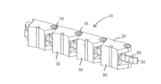
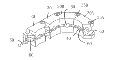
Fig. 1 is an isometric view according to the implant of one embodiment of the invention, and this implant has a tightening member and is engaged on the described implant;
Fig. 2 cuts the partial schematic diagram that shows that described tightening member is meshed with the ridge of described implant according to one embodiment of the invention of Fig. 1;
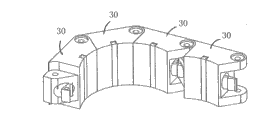
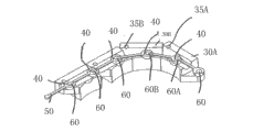
Fig. 3 is the isometric view according to the implant of one embodiment of the invention of Fig. 1, shows to be the configuration status that is in described flexing except a sections all;
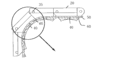
Fig. 4 is the partial side view of the crooked implant of cutting to show that described tightening member is meshed with the ridge of described implant according to one embodiment of the invention of Fig. 3;
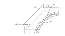
Fig. 5 is the regional zoomed-in view according to Fig. 4 one embodiment of the invention, and the zone by circle mark is to show the lock arrangement of described implant;
Fig. 6 a kind ofly is in the isometric view of straight configuration according to an implant of one embodiment of the invention, comprises that an implant and a tightening member are engaged on the described implant;
Fig. 7 is the isometric view that is in the configuration status of its flexing according to the implant of one embodiment of the invention shown in Figure 6;
Fig. 8 cuts to show the partial view that the protrusion of described tightening member is meshed with the groove of described implant according to Fig. 7 one embodiment of the invention;
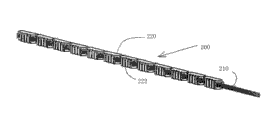
Fig. 9 is that according to another embodiment of the present invention a tightening member is engaged on the isometric view on the implant;
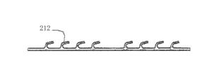
Figure 10 is the side view of tightening member shown in Figure 9;
Figure 11 is the cutaway view that is in a straight configuration according to two sections of the locking mechanism of the described implant of one embodiment of the invention shown in Fig. 9-10 and described implant;
Figure 12 is the cutaway view that is in the configuration status of a flexing according to two sections of the locking mechanism of the described implant of one embodiment of the invention shown in Fig. 9-10 and described implant;
Figure 13 is the flow chart of a kind of method of the present invention.
The specific embodiment
The present invention is a kind of implant of using in human body, for example uses in dissimilar operation on vertebra.Described implant has one firmly and lock arrangement firmly.The present invention comprises that also a corresponding method is used for being used for disposing described implant by a delivery catheter (conduit).Described implant can comprise an implant and a locking member.Described locking member can be included in the ridge on the described locking member, and this ridge matches along the engaged element on the sections of the bending section of described implant and described implant.Described ridge can be protrusion (bulges), tusk (teeth), shell fragment (elastic tabs) etc.Described engaged element can be step, slot, rectangular aperture etc.When each sections flexing, described ridge just in time drops on the described engaged element, and the described implant of having placed in vivo can not be opened.
Compare with prior art, the lock arrangement of the described implant of prior art only relates to pins sections in the described implant, implant of the present invention can relate to all sections of the flexing of pinning described implant, or pins in other embodiments at least two of flexing of described implant or at least three or at least three/1/one or at least four or at least one main sections.Further compare with prior art, the described implant of prior art does not have a lock arrangement firmly, implant of the present invention can with one enough firm and safe mode pin, when described implant in vivo, in case when being lockable with the configuration status of flexing, described implant can not be opened.Further compare with prior art, the described implant of prior art can be pinned the single tusk that can restore, and implant of the present invention can pin the ridge on the sections of described implant, matches with complemental groove on described locking member.Compare with prior art, described lock arrangement can comprise cooperating of a plurality of protrusions and a plurality of slots at least two sections or groove on a plurality of sections, and other embodiment on all sections.Further compare with prior art, described protrusion to the length between protrusion can be less than from a sections to its adjacent intersegmental described flex region to the length between bending area.So, the protrusion of described locking member can not be in straight configuration in slot, in case when described sections flexing entered the configuration status of described flexing, described protrusion can be locked in the slot.This make described lock arrangement extra firmly.
Principle and operation according to the medical treatment device with locking mechanism of the present invention and method are better illustrated with reference to accompanying drawing and corresponding the description.
Now forward accompanying drawing to, Fig. 1-5 has shown the medical treatment device of an embodiment, and described medical treatment device 10 comprises an implant 20, and implant 20 has a plurality of at flex region 35 interconnective sections, for example be that hinge interconnects with tying, so that present the configuration status of a straight configuration and a flexing.Described flex region 35 can comprise the structure of bending between a traditional hinge 35, integrally formed hinge or the another kind of sections that needs can be provided.As the part of described lock arrangement or locking mechanism, implant 20 forms with at least two engaged elements 40, each sections at least two different sections, and for example, sections 30A, sections 30B all have an engaged element 40.Preferably, at least three sections 30 have an engaged element 40, and pin a ridge 60.In other preferred embodiments, 1/3 sections 30 has an engaged element 40, and pins a ridge 60.In a preferred embodiment, at least one sections 30 has an engaged element 40 in every continuous four sections 30, and pins the ridge 60 of described elongated member 50.In other embodiments, described sections 30 more than half has an engaged element.In a preferred embodiment, this should be intelligible except each sections of a tip sections 30 can have an engaged element 40(in the described sections 30, also has an engaged element as can not definitely getting rid of described tip sections).
By the configuration of implant 20 and locking member 50, to apply tension force on tightening member 50, make the configuration status of the tightening member 50 trend described implants 20 of deflection from straight configuration to flexing.Elongated locking member 50 can pass along a conduit, and this conduit extends along implant 20.
Firm and firm locking are done in configuration by implant 20 and elongated locking member 50, prevent that the implant 10 that is positioned at other positions in vertebra or the body with flexion opens.This locking can be when the configuration status (as the part of implant 20) of locking member 50 deflections to flexing, the continuous sections 30 of each of implant 20 can flexing, and at least two ridges can be meshed with at least two engaged elements 40 of implant 20 and pin in the elongated locking member 50.After one or more continuous sections flexings and pinning, the sections 30 of each locking can keep pinning shape.Correspondingly, described lock arrangement is pinned the locking member 50 with respect to implant 20 effectively, therefore keeps implant 10 to be in vivo the configuration status of described flexing.
For example, in the described implant whenever at least two or whenever at least three or whenever 1/3 1/whenever at least four or every at least one main sections or every at least continuous four sections that go out can form with at least one engaged element so that pin described locking member.Further, described locking member can have a ridge, and the engagement corresponding with each engaged element of described implant of this ridge is to provide described lock arrangement.Another kind of situation, locking member 50 can have a plurality of diversified ridges 60 but be less than each engaged element 40 that a ridge is used for implant 20.In some preferred embodiments, the ridge that described locking member 50 can be more much more than the engaged element of described implant.For example, the ridge 60 of per quart can pin an engaged element.In some cases, even each sections 30 can have a plurality of engaged elements 40.
Described ridge 60 can comprise different types with engaged element 40, and type comprises the cross section type.In a word, the engaged element 40 of implant 20 is defined as widely and for example comprises ridge 60(that a step, a groove or other types can bear also " clamping " locking member 50, a protrusion, tusk or a shell fragment).In the embodiment shown in Fig. 1-5, engaged element 40 can be described as step 40, and this step can be clamped the dentation ridge 60 from locking member 50.Select structure and the size of ridge according to the mechanical property of material, so that enough restoring force and safety lock functions to be provided, and consider simultaneously biocompatibility.Corresponding engaged element can be used as element or the groove of any suitable position and implements, for example a ridge that makes progress or one the depression v-notch, perhaps both combinations.
In Fig. 6-8, described engaged element can be described as slot 40, and described ridge can be described as protrusion 60.Term " protrusion " is not limited to a circle (rounded) protrusion, even in certain embodiments, for example shown in Fig. 6-8, protrusion 60 can be spherical.Similarly, term " slot " is the slot of inessential finger one circle also, although the slot in Fig. 6-8 is circular.Further, can consider ridge 60, comprise protrusion 60, can be solid or hollow.
In the embodiment shown in Fig. 9-12, described ridge can be described as shell fragment 60, and engaged element 40 can be the groove of complementation.For example, each sections 30 can have the groove of at least one complementation, and when each sections during with flexing configuration status flexing, at least one shell fragment of tightening member 50 can pin the groove 40 of at least one complementation of each sections 30.
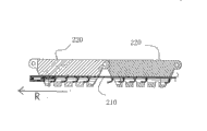
In Fig. 9-12, implant 200 can have the locking member 210 of sections 220 and a slide fastener shape, and locking member can firmly be attached on the tip sections 220, and all sections engagements of locking member and described implant 200.With the backward directions of a relative implant 200 haul locking member 210 near end.Implant 200 can have groove 222 or groove.Locking member 210 can be strip, can use metal material (for example, Nitinol, rustless steel) or plastics (for example, polyether-ether-ketone, ultra-high molecular weight polyethylene) implement, and have a series of shell fragment 212, spring-piece lock is on the corresponding engaged element 222 of implant 200.
Figure 11-12 has shown that actual locking mechanism is between two adjacent sections 220.Figure 11 shows that two sections 220 of implant 200 are in straight configuration, and wherein a v-notch or opening (being V-type in the present embodiment) are presented between two continuous sections 220.In case haul locking member 210 with respect to sections 220 with backward directions (consistent according to the R direction of arrow among Figure 11), it is owing between an axle of sections 220 and the conduit that described tightening member 20 passes deflection occurs that sections 220 can rotate.As the result who rotates, sections 220 is closely close each other, as shown in figure 12.Shown also that in Figure 12 described shell fragment 212 is locked in the groove 222, so sections 220 is attached to each other and firmly pins.
In certain embodiments, isolation locking member 50(or 210) a tension element can be used for drawing described implant with direction backward, and impels sections 30 flexings of described implant.In the sort of situation, described tension element will first cause described medical treatment device 10 flexings.Then, can haul locking member 50 and by the ridge 60 that matches with engaged element 40 to pin described medical treatment device.
Locking mechanism of the present invention can be further by using a plurality of locking members (50 or 210) to strengthen in the above-described embodiments.In this case, implant (200 or 20) and a plurality of engaged elements in a sections can be meshed with a plurality of engaged elements (220 or 40) on each sections (220 or 30) of implant and lock.In an example, described a plurality of locking members can be (side by side) strip materials arranged side by side.
In Fig. 6, when implant is in the state that stretches, the ridge 60 of locking member 50, be protrusion 60 in Fig. 6, can be applicable to or be engaged in, and in fact be not to be suitable for or to be engaged in engaged element 40, in Fig. 6, engaged element can be described as the slot 40 of implant 20.In Fig. 7, only these the sections 30 of flexing (30A, 30B) can have their engaged element or by the shared slot 40 of protrusion 60.Further, in Fig. 8, be easier to find out that protrusion 60 is in slot 40, be used for the sections 30 of flexing.Carefully check Fig. 6~Fig. 8 and Fig. 8 particularly, its be disclosed in a protrusion 60A in the described implant 10 to the distance between the nearest protrusion 60B can be less than the flection part 35A of a sections 30A to the distance between the flection part 35B of another adjacent sections 30B.Should be noted at Fig. 6 to embodiment shown in Figure 8, from a protrusion 60 to another protrusion 60(for example, to adjacent ridge 60) between distance be consistent substantially, and similarly, (for example, to adjacent slot 40) is consistent substantially from a slot to another slot.Yet, needing medical treatment device one is among the embodiment of spiral or on-plane surface or non-homogeneous bending, these the distance can be skimble-scamble, although on the sections of bending, slot to the distance between the slot still can and protrusion to the distance between the protrusion be complementary.
Notice that when continuous sections 30A, 30B, 30C and 30D flexing, the roughly arciform moulding of tightening member 50 can be crossed over a less arc of roughly arciform moulding that consists of than some hinges 35 of implant 20.This is because in a curved configuration state, and the tightening member 50 of implant 10 is the inside of most of implant 20, and some hinge 35(hinges particularly) inside.In this respect, " inside " is to be described as very to approach under the curved configuration state by implant 10(locked component 50 and implant 20) arc/annular center of consisting of of arciform moulding.So when being in described straight configuration, the described protrusion of at least some of described locking member can be positioned at the part hinge in the described slot outside, and the ridge of described locking member that is in the configuration status of described flexing is positioned at the slot of flexing sections.Each the sections 30 of flexing have a protrusion 60, to mesh corresponding slot.As can be seen from Figure 8, under the flexing configuration status, the flexing sections that each has a slot also has in a protrusion is applied to.
Although implant described in the embodiment shown in the drawings is in the upper flexing of a two dimensional surface (plane), so that the elongation direction of implant 10 can be described as with this hinge coplanar, and perpendicular to described hinge, the present invention is equal to and is applied in on-plane surface or screw type implant 10, for example, the elongation direction of implant move to from the tip sections of a flexing configuration status that is in flexing one near the sections of flexing, this elongation direction is not orthogonal to the described hinge of the sections of described flexing.The spiral configuration of implant and the example that does not have lock arrangement of the present invention, the PCT patent application publication number WO2006/072941(that announces on July 13rd, 2006 checks Fig. 9 A, 9B and Figure 10 of the 17th page) in existing the description, its publication thereby with its whole introducing here as a reference.This publication has also been described the general features of sections 30 and implant 10, although it does not have firm safe lock arrangement of the present invention.
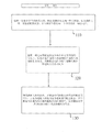
Referring to Figure 13, the present invention also can be described as a method 100 and be used for configuration one implant in a main body body.Method 100 can comprise first step: an implant is provided, comprises that a plurality of sections hinge knot ground interconnects down to presenting a straight configuration, and deflection to be to present the configuration status of a flexing, a plurality of described sections have an engaged element separately.In further step 120, method 100 can relate to provides a locking member to be anchored on the tip sections, extends in along described implant on the elongation direction of described implant.Described locking member can have ridge, and is corresponding with each engaged element of described implant.In the step 130 of method, implant can enter in the body of main body.Further, tension force backward can be applied on the described locking member, so that described implant deflection is to the configuration status of described flexing.So described ridge can match with corresponding engaged element, so that pin the corresponding sections that is the flexing configuration status.Some variations (version) of method 100 also can comprise from the anchor of locking member and to discharge described locking member, and the step that described locking member is withdrawed from from described medical treatment device.
On structure, the flex region 35 between sections 30 can be implemented in the method for wide region.More preferably, intersegmental interconnect can be by in the injection process or in the forming process with being hinged that the integrally formed integral hinge 35 of sections 30 obtains, or obtain by the mode from the starting block excision groove of material.Described groove can be v-notch, parallel limit, perhaps any forms that other are fit to.More preferably, can adopt the V-type slot, so that the spacing that the collocation form of the bending of described implant has between sections is substantially closed.Yet optional embodiment for example when the separable structure (for example " spine (backbone) ") that adheres to sections, when hinged interconnecting is provided, also falls into protection scope of the present invention.In the example of back, described spine can be to make from the different material of sections self, selects according to being used for intentionally.The material that is used for spine includes but not limited to metal material, multiple plastics, other polymer, and fabric.
The configuration status of described flexing is the collocation form of clinodactyly (curved) also.Yet " flexing " needn't relate to the true bending of sections here, although may have in certain embodiments so crooked.And the collocation form of described bending should not be construed and represents a perfectly bending, particularly checks the sections of relative minority.So, the collocation form of described flexing, its collocation form that is called as the bending of implant 10 is roughly arc form, and it can typically extend and rotates about 180 and spend to form the form that is roughly " U-shaped " that looks.Here the term " U-shaped " that adopts refers to arbitrary shape generally, as long as have rotation roughly 180 the degree (for example, 180 the degree add deduct 20 the degree) mid portion, and the concrete shape, geometry or the scope that need not the certain illustrated two side portions are (additionally, should be noted that letter " U " is asymmetric certainly in many fonts).
Significant be, content described above only is as example, it all is possible also having many other embodiments, they fall within the defined protection scope of the present invention of accompanying claim.
Claims (23)
1. medical treatment device comprises:
(a) implant with a plurality of sections, described sections interconnects so that present the state that stretches and the configuration status of a flexing, described implant forms has at least two engaged elements, and each sections has an engaged element at least two different sections; And
(b) an elongated locking member is anchored on the sections of described implant, and it is corresponding with described at least two engaged elements that described locking member has at least two ridges,
It is characterized in that, disposing described implant and described locking member has the function of locking, so that work as described locking member deflection to the configuration status that reaches described flexing, described at least two ridges of described locking member are meshed with at least two engaged elements of described implant and lock, after continuous sections flexing and locking, each locking member is kept the locking shape, described lock arrangement effectively locking phase for the locking member of described implant, so keep described implant to be in the configuration status of described flexing.
2. a kind of medical treatment device as claimed in claim 1, it is characterized in that, described locking member is anchored on the tip sections of described implant, and dispose described implant and locking member, so that be applied to the configuration status of tension force tendency from described state deflection of stretching to described flexing on the described locking member.
3. a kind of medical treatment device as claimed in claim 1, it is characterized in that, at least three sections of described implant form with at least one engaged element and a tightening member, and the engagement corresponding with at least one engaged element of described implant of described tightening member is so that provide described lock arrangement.
4. a kind of medical treatment device as claimed in claim 1, it is characterized in that, at least three of described implant/one sections forms with at least one engaged element and a tightening member, and the engagement corresponding with at least one engaged element of described implant of described tightening member is so that provide described lock arrangement.
5. a kind of medical treatment device as claimed in claim 1 is characterized in that, has a sections to have an engaged element in per four continuous sections of described implant, and locks a corresponding ridge of described tightening member.
6. a kind of medical treatment device as claimed in claim 1, it is characterized in that, all sections of described implant form with at least one engaged element except the tip sections, and described tightening member has a ridge, ridge and engagement corresponding with at least two engaged elements of described implant is to provide described lock arrangement.
7. a kind of medical treatment device as claimed in claim 1 is characterized in that, a main sections forms with at least one engaged element, and described tightening member has a ridge, and ridge is corresponding with described at least one engaged element.
8. a kind of medical treatment device as claimed in claim 1 is characterized in that, described ridge is tusk, and engaged element is step.
9. a kind of medical treatment device as claimed in claim 1 is characterized in that, described ridge is shell fragment, and engaged element is complementary groove.
10. a kind of medical treatment device as claimed in claim 9, it is characterized in that, each sections has groove and at least one shell fragment of at least one complementation, and when each sections bending was in the configuration status of described flexing, described at least one shell fragment locked the groove of at least one complementation.
11. a kind of medical treatment device as claimed in claim 1 is characterized in that, further comprises a conduit size bearing described implant, and keeps described implant and be in the described state that stretches.
12. a medical treatment device comprises:
(a) implant with a plurality of sections, described sections interconnect so that present the state that stretches and the configuration status of a flexing, and described implant forms has at least two grooves, and each sections has a groove at least two different sections; And
(b) an elongated locking member is anchored on the sections of described implant, and it is corresponding with described at least two protrusions that described locking member has at least two protrusions,
It is characterized in that, dispose described implant and described locking member has lock function, so that work as described locking member deflection to the configuration status that reaches described flexing, at least two protrusions of described locking member are meshed with at least two grooves of described implant and lock, described lock arrangement locks described locking member effectively with respect to the implant that a plurality of sections are arranged, so keep the configuration status that described implant is in described flexing.
13. a kind of medical treatment device as claimed in claim 12, it is characterized in that, described locking member is anchored on the tip sections of described implant, and dispose described implant and locking member, so that be applied to the configuration status of tension force tendency from described state deflection of stretching to described flexing on the described locking member.
14. a kind of medical treatment device as claimed in claim 12, it is characterized in that at least one demisection of described implant forms with at least one groove and a tightening member, described tightening member has a protrusion, protrusion is corresponding with all described grooves, so that described lock arrangement to be provided.
15. a kind of medical treatment device as claimed in claim 12 is characterized in that, the distance of the protrusion from protrusion to nearest neighbor is shorter to the distance of the bending area of another adjacent sections than the bending area from a sections.
16. a kind of medical treatment device as claimed in claim 12 is characterized in that, and is unanimous on the whole to the distance between protrusion from protrusion, and unanimous on the whole to the distance between groove from groove.
17. a kind of medical treatment device as claimed in claim 12, it is characterized in that, at least some ridges that are in the described tightening member of straight configuration are positioned at the part flex region, flex region is in the outside of described groove, and the protrusion of described locking member that is in the configuration status of flexing is positioned at the groove of the sections of flexing.
18. a kind of medical treatment device as claimed in claim 12 is characterized in that, the sections of each flexing that is in the configuration status of flexing has a groove, also has a protrusion and is positioned at groove.
19. a kind of medical treatment device as claimed in claim 12 is characterized in that described medical treatment device is spiral.
20. a kind of medical treatment device as claimed in claim 12 is characterized in that, further comprises a conduit, the size of conduit to be bearing described medical treatment device, and keeps described implant and be in described straight configuration.
21. a kind of medical treatment device as claimed in claim 12 is characterized in that described protrusion and groove are spherical.
22. a method that is used for being configured in the described medical treatment device in the main body body comprises:
(a) provide a plant with a plurality of sections, interconnect so that present a straight configuration, and deflection presents the configuration status of a flexing, each sections of a plurality of described sections has an engaged element;
(b) provide on the sections that a locking member is anchored at least two different sections, and extend in along described implant on the elongation direction of described implant, it is corresponding with each described engaged element that described locking member has ridge; And
(c) described implant is entered in the body of described main body, and apply backward tension force on described locking member, so that described implant deflection is to the configuration status of described flexing,
It is characterized in that described ridge matches with corresponding described engaged element, so that pin the corresponding sections of the configuration status that is in described flexing.
23. method as claimed in claim 22 is characterized in that, further comprise discharging described locking member from the anchor of described locking member, and described locking member withdraws from from described medical treatment device.
Applications Claiming Priority (3)
| Application Number | Priority Date | Filing Date | Title |
|---|---|---|---|
| US30485710P | 2010-02-16 | 2010-02-16 | |
| US61/304,857 | 2010-02-16 | ||
| PCT/IB2011/050648 WO2011101793A1 (en) | 2010-02-16 | 2011-02-16 | Medical device lock mechanism |
Publications (1)
| Publication Number | Publication Date |
|---|---|
| CN102933178A true CN102933178A (en) | 2013-02-13 |
Family
ID=43919605
Family Applications (1)
| Application Number | Title | Priority Date | Filing Date |
|---|---|---|---|
| CN2011800190744A Pending CN102933178A (en) | 2010-02-16 | 2011-02-16 | Medical device lock mechanism |
Country Status (9)
| Country | Link |
|---|---|
| US (3) | US9017408B2 (en) |
| EP (2) | EP2536363A1 (en) |
| JP (1) | JP5774028B2 (en) |
| KR (1) | KR20120138762A (en) |
| CN (1) | CN102933178A (en) |
| CA (1) | CA2789961A1 (en) |
| IL (2) | IL221455A0 (en) |
| RU (1) | RU2012138578A (en) |
| WO (2) | WO2011101793A1 (en) |
Cited By (6)
| Publication number | Priority date | Publication date | Assignee | Title |
|---|---|---|---|---|
| CN103465020A (en) * | 2013-09-11 | 2013-12-25 | 昆山科森科技有限公司 | Accurate assembly device for medical assembly |
| CN104416355A (en) * | 2013-09-11 | 2015-03-18 | 昆山科森科技股份有限公司 | Assembling device for medical instrument |
| CN104644291A (en) * | 2013-11-18 | 2015-05-27 | 宝楠生技股份有限公司 | Memory-based intervertebral fusion fixing device |
| CN104921849A (en) * | 2015-07-15 | 2015-09-23 | 王洪伟 | Interbody fusion cage |
| CN106308983A (en) * | 2016-08-31 | 2017-01-11 | 广州爱锘德医疗器械有限公司 | Fusion cage, operating instrument and vertebrae fusion device |
| WO2022178759A1 (en) * | 2021-02-25 | 2022-09-01 | 上海三友医疗器械股份有限公司 | Fusion cage and installation tool therefor |
Families Citing this family (60)
| Publication number | Priority date | Publication date | Assignee | Title |
|---|---|---|---|---|
| US6793678B2 (en) | 2002-06-27 | 2004-09-21 | Depuy Acromed, Inc. | Prosthetic intervertebral motion disc having dampening |
| MXPA05008653A (en) | 2003-02-14 | 2006-04-27 | Depuy Spine Inc | In-situ formed intervertebral fusion device and method. |
| US20040267367A1 (en) | 2003-06-30 | 2004-12-30 | Depuy Acromed, Inc | Intervertebral implant with conformable endplate |
| US20070162132A1 (en) | 2005-12-23 | 2007-07-12 | Dominique Messerli | Flexible elongated chain implant and method of supporting body tissue with same |
| US8034110B2 (en) | 2006-07-31 | 2011-10-11 | Depuy Spine, Inc. | Spinal fusion implant |
| US8105382B2 (en) | 2006-12-07 | 2012-01-31 | Interventional Spine, Inc. | Intervertebral implant |
| US9039768B2 (en) | 2006-12-22 | 2015-05-26 | Medos International Sarl | Composite vertebral spacers and instrument |
| FR2917287B1 (en) * | 2007-06-15 | 2010-09-03 | Ldr Medical | INTERVERTEBRAL PROSTHESIS |
| US8900307B2 (en) | 2007-06-26 | 2014-12-02 | DePuy Synthes Products, LLC | Highly lordosed fusion cage |
| US7922767B2 (en) | 2007-07-07 | 2011-04-12 | Jmea Corporation | Disk fusion implant |
| US20090088789A1 (en) | 2007-09-28 | 2009-04-02 | O'neil Michael J | Balloon With Shape Control For Spinal Procedures |
| EP2471493A1 (en) | 2008-01-17 | 2012-07-04 | Synthes GmbH | An expandable intervertebral implant and associated method of manufacturing the same |
| US20090248092A1 (en) | 2008-03-26 | 2009-10-01 | Jonathan Bellas | Posterior Intervertebral Disc Inserter and Expansion Techniques |
| KR20110003475A (en) | 2008-04-05 | 2011-01-12 | 신세스 게엠바하 | Expandable intervertebral implant |
| US9526620B2 (en) | 2009-03-30 | 2016-12-27 | DePuy Synthes Products, Inc. | Zero profile spinal fusion cage |
| US9028553B2 (en) | 2009-11-05 | 2015-05-12 | DePuy Synthes Products, Inc. | Self-pivoting spinal implant and associated instrumentation |
| US9168138B2 (en) | 2009-12-09 | 2015-10-27 | DePuy Synthes Products, Inc. | Aspirating implants and method of bony regeneration |
| US9393129B2 (en) | 2009-12-10 | 2016-07-19 | DePuy Synthes Products, Inc. | Bellows-like expandable interbody fusion cage |
| US9592063B2 (en) | 2010-06-24 | 2017-03-14 | DePuy Synthes Products, Inc. | Universal trial for lateral cages |
| US8979860B2 (en) | 2010-06-24 | 2015-03-17 | DePuy Synthes Products. LLC | Enhanced cage insertion device |
| TW201215379A (en) | 2010-06-29 | 2012-04-16 | Synthes Gmbh | Distractible intervertebral implant |
| US20120078373A1 (en) | 2010-09-23 | 2012-03-29 | Thomas Gamache | Stand alone intervertebral fusion device |
| US11529241B2 (en) | 2010-09-23 | 2022-12-20 | DePuy Synthes Products, Inc. | Fusion cage with in-line single piece fixation |
| US20120078372A1 (en) | 2010-09-23 | 2012-03-29 | Thomas Gamache | Novel implant inserter having a laterally-extending dovetail engagement feature |
| US9402732B2 (en) | 2010-10-11 | 2016-08-02 | DePuy Synthes Products, Inc. | Expandable interspinous process spacer implant |
| EP3485851B1 (en) | 2011-03-22 | 2021-08-25 | DePuy Synthes Products, LLC | Universal trial for lateral cages |
| WO2013043850A2 (en) * | 2011-09-20 | 2013-03-28 | The University Of Toledo | Expandable inter-vertebral cage and method of installing same |
| US9198765B1 (en) | 2011-10-31 | 2015-12-01 | Nuvasive, Inc. | Expandable spinal fusion implants and related methods |
| US9226764B2 (en) | 2012-03-06 | 2016-01-05 | DePuy Synthes Products, Inc. | Conformable soft tissue removal instruments |
| US9271836B2 (en) | 2012-03-06 | 2016-03-01 | DePuy Synthes Products, Inc. | Nubbed plate |
| WO2014033651A1 (en) * | 2012-08-29 | 2014-03-06 | Nlt Spine Ltd | Method and system for implants |
| US9445918B1 (en) | 2012-10-22 | 2016-09-20 | Nuvasive, Inc. | Expandable spinal fusion implants and related instruments and methods |
| US10182921B2 (en) | 2012-11-09 | 2019-01-22 | DePuy Synthes Products, Inc. | Interbody device with opening to allow packing graft and other biologics |
| US10022245B2 (en) | 2012-12-17 | 2018-07-17 | DePuy Synthes Products, Inc. | Polyaxial articulating instrument |
| US9522070B2 (en) | 2013-03-07 | 2016-12-20 | Interventional Spine, Inc. | Intervertebral implant |
| US9795493B1 (en) | 2013-03-15 | 2017-10-24 | Nuvasive, Inc. | Expandable intervertebral implant and methods of use thereof |
| WO2015009998A1 (en) * | 2013-07-18 | 2015-01-22 | The University Of Toledo | Expandable inter-vertebral cage and method of installing same |
| US9901457B2 (en) | 2014-10-16 | 2018-02-27 | Jmea Corporation | Coiling implantable prostheses |
| EP3242632B1 (en) * | 2015-01-09 | 2021-02-24 | Formae, Inc. | Rigid segmented flexible anchors |
| US11426290B2 (en) | 2015-03-06 | 2022-08-30 | DePuy Synthes Products, Inc. | Expandable intervertebral implant, system, kit and method |
| USD790310S1 (en) | 2015-09-21 | 2017-06-27 | Lawrence St. Peter | Handle adapter for a bench vice |
| US11833034B2 (en) | 2016-01-13 | 2023-12-05 | Shifamed Holdings, Llc | Prosthetic cardiac valve devices, systems, and methods |
| CN109688980B (en) | 2016-06-28 | 2022-06-10 | Eit 新兴移植技术股份有限公司 | Expandable and angularly adjustable intervertebral cage with articulation joint |
| EP4233801A3 (en) | 2016-06-28 | 2023-09-06 | Eit Emerging Implant Technologies GmbH | Expandable, angularly adjustable intervertebral cages |
| US10888433B2 (en) | 2016-12-14 | 2021-01-12 | DePuy Synthes Products, Inc. | Intervertebral implant inserter and related methods |
| US10398563B2 (en) | 2017-05-08 | 2019-09-03 | Medos International Sarl | Expandable cage |
| US11344424B2 (en) | 2017-06-14 | 2022-05-31 | Medos International Sarl | Expandable intervertebral implant and related methods |
| US10940016B2 (en) | 2017-07-05 | 2021-03-09 | Medos International Sarl | Expandable intervertebral fusion cage |
| US10966843B2 (en) | 2017-07-18 | 2021-04-06 | DePuy Synthes Products, Inc. | Implant inserters and related methods |
| US11045331B2 (en) | 2017-08-14 | 2021-06-29 | DePuy Synthes Products, Inc. | Intervertebral implant inserters and related methods |
| NL2019711B1 (en) * | 2017-10-12 | 2019-04-23 | Am Solutions Holding B V | A spinal implant |
| WO2020073050A1 (en) | 2018-10-05 | 2020-04-09 | Shifamed Holdings, Llc | Prosthetic cardiac valve devices, systems, and methods |
| US20210378823A1 (en) * | 2018-10-19 | 2021-12-09 | Shifamed Holdings, Llc | Adjustable medical device |
| US11446156B2 (en) | 2018-10-25 | 2022-09-20 | Medos International Sarl | Expandable intervertebral implant, inserter instrument, and related methods |
| EP3941391A4 (en) | 2019-03-19 | 2022-11-23 | Shifamed Holdings, LLC | Prosthetic cardiac valve devices, systems, and methods |
| US11426286B2 (en) | 2020-03-06 | 2022-08-30 | Eit Emerging Implant Technologies Gmbh | Expandable intervertebral implant |
| CN112120778B (en) * | 2020-09-17 | 2022-03-25 | 山东冠龙医疗用品有限公司 | Centrum struts filling device and propeller |
| US11850160B2 (en) | 2021-03-26 | 2023-12-26 | Medos International Sarl | Expandable lordotic intervertebral fusion cage |
| US11752009B2 (en) | 2021-04-06 | 2023-09-12 | Medos International Sarl | Expandable intervertebral fusion cage |
| CN113244027B (en) * | 2021-06-25 | 2021-09-24 | 珠海维尔康生物科技有限公司 | Minimally invasive fence type deformable fusion device used under endoscope |
Citations (4)
| Publication number | Priority date | Publication date | Assignee | Title |
|---|---|---|---|---|
| WO2008103832A2 (en) * | 2007-02-21 | 2008-08-28 | Benvenue Medical, Inc. | Devices for treating the spine |
| WO2008103781A2 (en) * | 2007-02-21 | 2008-08-28 | Benvenue Medical, Inc. | Devices for treating the spine |
| US20080221687A1 (en) * | 2007-03-08 | 2008-09-11 | Zimmer Spine, Inc. | Deployable segmented tlif device |
| US20080249628A1 (en) * | 2007-04-09 | 2008-10-09 | Moti Altarac | Multi-component interbody device |
Family Cites Families (12)
| Publication number | Priority date | Publication date | Assignee | Title |
|---|---|---|---|---|
| EP1833375B1 (en) | 2005-01-05 | 2013-07-17 | NLT Spine Ltd. | Straight introduction device that assumes curved configuration |
| US20070162135A1 (en) | 2005-06-15 | 2007-07-12 | Jerome Segal | Mechanical apparatus and method for artificial disc replacement |
| EP1924227B1 (en) | 2005-08-16 | 2014-12-17 | Benvenue Medical, Inc. | Spinal tissue distraction devices |
| FI20065474L (en) | 2006-07-04 | 2008-01-05 | Head Inhimillinen Tekijae Oy | A method for processing audio information |
| US8025697B2 (en) | 2006-09-21 | 2011-09-27 | Custom Spine, Inc. | Articulating interbody spacer, vertebral body replacement |
| US7947078B2 (en) * | 2007-01-09 | 2011-05-24 | Nonlinear Technologies Ltd. | Devices for forming curved or closed-loop structures |
| WO2008084479A2 (en) * | 2007-01-09 | 2008-07-17 | Nonlinear Technologies Ltd. | Devices for forming curved or closed-loop structures |
| US20090012612A1 (en) | 2007-04-10 | 2009-01-08 | David White | Devices and methods for push-delivery of implants |
| FR2917287B1 (en) * | 2007-06-15 | 2010-09-03 | Ldr Medical | INTERVERTEBRAL PROSTHESIS |
| ES2374760T3 (en) | 2007-08-09 | 2012-02-21 | Nonlinear Technologies Ltd. | DEVICE FOR THE DISTRACTION OF SPOUS APOPHYSIS. |
| US8951546B2 (en) | 2008-12-23 | 2015-02-10 | Surmodics Pharmaceuticals, Inc. | Flexible implantable composites and implants comprising same |
| CA2805476A1 (en) * | 2010-07-21 | 2012-01-26 | Nlt Spine Ltd. | Spinal surgery implants and delivery system |
-
2011
- 2011-02-16 CN CN2011800190744A patent/CN102933178A/en active Pending
- 2011-02-16 US US13/579,292 patent/US9017408B2/en active Active
- 2011-02-16 CA CA 2789961 patent/CA2789961A1/en not_active Abandoned
- 2011-02-16 WO PCT/IB2011/050648 patent/WO2011101793A1/en active Application Filing
- 2011-02-16 KR KR20127023817A patent/KR20120138762A/en not_active Application Discontinuation
- 2011-02-16 US US13/521,747 patent/US20150112436A1/en not_active Abandoned
- 2011-02-16 RU RU2012138578/14A patent/RU2012138578A/en not_active Application Discontinuation
- 2011-02-16 EP EP20110707919 patent/EP2536363A1/en not_active Withdrawn
- 2011-02-16 JP JP2012552517A patent/JP5774028B2/en active Active
- 2011-02-16 WO PCT/IB2011/050647 patent/WO2011101792A1/en active Application Filing
- 2011-02-16 EP EP20110708330 patent/EP2536364A1/en not_active Withdrawn
-
2012
- 2012-08-14 IL IL221455A patent/IL221455A0/en unknown
- 2012-08-14 IL IL221457A patent/IL221457A0/en unknown
-
2015
- 2015-03-22 US US14/664,867 patent/US9662222B2/en active Active
Patent Citations (4)
| Publication number | Priority date | Publication date | Assignee | Title |
|---|---|---|---|---|
| WO2008103832A2 (en) * | 2007-02-21 | 2008-08-28 | Benvenue Medical, Inc. | Devices for treating the spine |
| WO2008103781A2 (en) * | 2007-02-21 | 2008-08-28 | Benvenue Medical, Inc. | Devices for treating the spine |
| US20080221687A1 (en) * | 2007-03-08 | 2008-09-11 | Zimmer Spine, Inc. | Deployable segmented tlif device |
| US20080249628A1 (en) * | 2007-04-09 | 2008-10-09 | Moti Altarac | Multi-component interbody device |
Cited By (7)
| Publication number | Priority date | Publication date | Assignee | Title |
|---|---|---|---|---|
| CN103465020A (en) * | 2013-09-11 | 2013-12-25 | 昆山科森科技有限公司 | Accurate assembly device for medical assembly |
| CN104416355A (en) * | 2013-09-11 | 2015-03-18 | 昆山科森科技股份有限公司 | Assembling device for medical instrument |
| CN104416355B (en) * | 2013-09-11 | 2017-01-11 | 昆山科森科技股份有限公司 | Assembling device for medical instrument |
| CN104644291A (en) * | 2013-11-18 | 2015-05-27 | 宝楠生技股份有限公司 | Memory-based intervertebral fusion fixing device |
| CN104921849A (en) * | 2015-07-15 | 2015-09-23 | 王洪伟 | Interbody fusion cage |
| CN106308983A (en) * | 2016-08-31 | 2017-01-11 | 广州爱锘德医疗器械有限公司 | Fusion cage, operating instrument and vertebrae fusion device |
| WO2022178759A1 (en) * | 2021-02-25 | 2022-09-01 | 上海三友医疗器械股份有限公司 | Fusion cage and installation tool therefor |
Also Published As
| Publication number | Publication date |
|---|---|
| JP2013526898A (en) | 2013-06-27 |
| US9017408B2 (en) | 2015-04-28 |
| EP2536363A1 (en) | 2012-12-26 |
| RU2012138578A (en) | 2014-03-27 |
| IL221457A0 (en) | 2012-10-31 |
| US20150112436A1 (en) | 2015-04-23 |
| EP2536364A1 (en) | 2012-12-26 |
| US20150209151A1 (en) | 2015-07-30 |
| WO2011101793A1 (en) | 2011-08-25 |
| CA2789961A1 (en) | 2011-08-25 |
| US20130035762A1 (en) | 2013-02-07 |
| IL221455A0 (en) | 2012-10-31 |
| WO2011101792A1 (en) | 2011-08-25 |
| JP5774028B2 (en) | 2015-09-02 |
| US9662222B2 (en) | 2017-05-30 |
| KR20120138762A (en) | 2012-12-26 |
Similar Documents
| Publication | Publication Date | Title |
|---|---|---|
| CN102933178A (en) | Medical device lock mechanism | |
| US20110093072A1 (en) | Devices for forming curved or closed-loop structures | |
| AU2021282492B2 (en) | Device and method for reinforcement of a facet | |
| CN101790355B (en) | Device and method for vertebrae spinous process traction | |
| US7846210B2 (en) | Minimally invasive interbody device assembly | |
| EP2099390A2 (en) | Devices for forming curved or closed-loop structures | |
| JP6355925B2 (en) | Intervertebral joint fusion implant and fusion method | |
| JP5555711B2 (en) | Methods and devices for limiting spinal segment flexion and extension | |
| CN105517501A (en) | Bone fixation device | |
| US20190167260A1 (en) | Fixation Device | |
| CN106999180A (en) | Two-part anchor with anchor inserter | |
| DE102011001590A1 (en) | Facet joint implant | |
| WO2017152026A1 (en) | Push-in anchor | |
| DE202011000699U1 (en) | Facet joint implant |
Legal Events
| Date | Code | Title | Description |
|---|---|---|---|
| C06 | Publication | ||
| PB01 | Publication | ||
| C10 | Entry into substantive examination | ||
| SE01 | Entry into force of request for substantive examination | ||
| C02 | Deemed withdrawal of patent application after publication (patent law 2001) | ||
| WD01 | Invention patent application deemed withdrawn after publication |
Application publication date: 20130213 |