CN102692981A - Wind scooper combination - Google Patents
Wind scooper combination Download PDFInfo
- Publication number
- CN102692981A CN102692981A CN2011100730068A CN201110073006A CN102692981A CN 102692981 A CN102692981 A CN 102692981A CN 2011100730068 A CN2011100730068 A CN 2011100730068A CN 201110073006 A CN201110073006 A CN 201110073006A CN 102692981 A CN102692981 A CN 102692981A
- Authority
- CN
- China
- Prior art keywords
- wind scooper
- top board
- combination
- wind
- scooper
- Prior art date
- Legal status (The legal status is an assumption and is not a legal conclusion. Google has not performed a legal analysis and makes no representation as to the accuracy of the status listed.)
- Pending
Links
- 238000010586 diagram Methods 0.000 description 1
Images


Classifications
-
- G—PHYSICS
- G06—COMPUTING; CALCULATING OR COUNTING
- G06F—ELECTRIC DIGITAL DATA PROCESSING
- G06F1/00—Details not covered by groups G06F3/00 - G06F13/00 and G06F21/00
- G06F1/16—Constructional details or arrangements
- G06F1/20—Cooling means
Abstract
The invention discloses a wind scooper combination, which comprises a first wind scooper and a second wind scooper connected to the first wind scooper in a detachable manner, wherein a sunken part is formed on the inner side of the first wind scooper around the edge of the rear end; a plurality of clamping slots are formed on the outer side of the rear end of the first scooper; a flange extends out of the inner side of the second wind scooper around the edge of the front end and is clamped on the sunken part of the first wind scooper; and a plurality of clamping blocks are protruded on the outer side of the front end of the second wind scooper and clamped on the corresponding clamping slots of the first wind scooper. According to the wind scooper combination, the first wind scooper or the second wind scooper can be used independently according to the requirement, or the second wind scooper is connected to the first wind scooper, so that the wind guiding length is changed.
Description
Technical field
The present invention relates to a kind of wind scooper combination.
Background technology
Existing wind scooper length is certain, and it can not come variation length according to the radiating requirements of computer housing.
Summary of the invention
Seeing that more than, but be necessary to provide a kind of wind scooper of variation length to make up.
A kind of wind scooper combination; Comprise that one first wind scooper and removably is connected in second wind scooper of this first wind scooper; The inboard of this first wind scooper is provided with a recess around back edge; The outside of the rear end of this first wind scooper is provided with some draw-in grooves, and the inboard of this second wind scooper extends to form a flange around front edge, in order to be placed in the recess of this first wind scooper; The outside of the front end of this second wind scooper is convexly equipped with some fixture blocks, in order to be placed in the corresponding draw-in groove of this first wind scooper.
Compare prior art, this wind scooper combination can be used this first wind scooper or second wind scooper as required separately, maybe this second wind scooper is connected to this first wind scooper and uses together, to change the length of wind-guiding.
Description of drawings
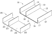
Fig. 1 is the three-dimensional assembly diagram of the preferred embodiments of wind scooper combination of the present invention.
Fig. 2 is the three-dimensional exploded view of Fig. 1 in other direction.
Fig. 3 is the other direction view of Fig. 2.
The main element symbol description
| |
10 |
| |
11、21 |
| |
12、22 |
| |
13、23 |
| First air-guiding |
14、24 |
| Second air-guiding |
15、25 |
| Recess | 16 |
| Draw-in |
17 |
| The |
18 |
| |
20 |
| |
26 |
| |
27 |
| |
28 |
Following embodiment will combine above-mentioned accompanying drawing to further specify the present invention.
Embodiment
Please with reference to Fig. 1, the preferred embodiments of wind scooper combination of the present invention comprises one first wind scooper 10 and one second wind scooper 20.
Please with reference to Fig. 2 and Fig. 3, this first wind scooper 10 comprise a top board 11, the biside plate 12 that extends vertically downward from the limit, two opposite sides of this top board 11 respectively and from the bottom of this top board 11 to a dividing plate 13 parallel that extends below with this biside plate 12.This dividing plate 13 and this top board 11 and wherein side plate 12 be encircled into one first air-guiding aisle 14, and be encircled into one second air-guiding aisle 15 with this top board 11 and another side plate 12 wherein.This top board 11 and this biside plate 12 form a recess 16 around the inclination of the back edge of this first wind scooper 10 in the edge of rear end to inscribe.The outside of this top board 11 and this biside plate 12 is provided with the trapezoidal draw-in groove 17 that is through to back edge of at least one depression respectively in the adjacent back end place.The width of each draw-in groove 17 reduces in the past backward gradually.The rear end of this dividing plate 13 is convexly equipped with the V-shaped holding section 18 of xsect that extends longitudinally.
The biside plate 22 that this second wind scooper 20 comprises a top board 21, extend from the limit, two opposite sides of this top board 21 respectively vertically downward and from the bottom of this top board 21 to a dividing plate 23 parallel that extends below with this biside plate 22.This dividing plate 23 and this top board 21 and wherein side plate 22 be encircled into one first air-guiding aisle 24, and be encircled into one second air-guiding aisle 25 with this top board 21 and another side plate 22 wherein.This top board 21 and this biside plate 22 in the edge of front end near the place, inboard stretch out form one have an inclined-plane the flange 26 around the front edge of this second wind scooper 20.The outside of this top board 21 and this biside plate 22 is convexly equipped with at least one trapezoidal fixture block 27 respectively forward in the front end place.The width of each fixture block 27 from after become big forward gradually.The front end of this dividing plate 23 is provided with the V-shaped groove 28 of xsect that extends longitudinally.
During assembling; This second wind scooper 20 is connected to the rear end of this first wind scooper 10; Make the flange 26 of this second wind scooper 20 be placed in the recess 16 of this first wind scooper 10; The holding section 18 of the dividing plate 13 of first wind scooper 10 snaps in the groove 28 of the dividing plate 23 of this second wind scooper 20, and makes the fixture block 27 of this second wind scooper 20 be placed in the corresponding draw-in groove 17 of this first wind scooper 10 respectively.At this moment, this wind scooper combination assembling is accomplished.First, second air-guiding aisle 14,15 of this first wind scooper 10 is respectively over against first, second air-guiding aisle 24,25 of this second wind scooper 20.
During use, the user can use this first wind scooper 10 or second wind scooper 20 as required separately, maybe this second wind scooper 20 is connected to this first wind scooper 10 and uses together.Because the junction of this first, second wind scooper 10,20 is provided with recess 16 and flange 26, holding section 18 and the groove 28 of holding each other, not distinguished and admirable can not the spilling of this wind scooper combination of flowing through from the junction of this first, second wind scooper 10,20.
Claims (4)
1. wind scooper combination; Comprise that one first wind scooper and removably is connected in second wind scooper of this first wind scooper; The inboard of this first wind scooper is provided with a recess around edge, its rear end; The outside of the rear end of this first wind scooper is provided with some draw-in grooves, and the inboard of this second wind scooper extends to form a flange around its front edge, in order to be placed in the recess of this first wind scooper; The outside of the front end of this second wind scooper is convexly equipped with some fixture blocks, in order to be placed in the corresponding draw-in groove of this first wind scooper.
2. wind scooper combination as claimed in claim 1; It is characterized in that: this first wind scooper comprises a top board and the biside plate that extends vertically downward from the limit, two opposite sides of this top board respectively; These draw-in grooves hollowly are located at the rear end in the outside of this top board and this biside plate respectively; This second wind scooper comprises a top board and the biside plate that extends vertically downward from the limit, two opposite sides of this top board respectively, and these fixture blocks are convexly set in the front end in the outside of top board and the side plate of this second wind scooper respectively.
3. wind scooper as claimed in claim 2 combination, it is characterized in that: each draw-in groove and fixture block roughly are trapezoidal, the width of each draw-in groove reduces in the past backward gradually, the width of each fixture block from after become big forward gradually.
4. wind scooper combination as claimed in claim 2; It is characterized in that: this first wind scooper also comprise one from the bottom of its top board to the dividing plate parallel that extends below with its biside plate; The rear end of this dividing plate is convexly equipped with the V-shaped holding section of xsect that extends longitudinally; This second wind scooper also comprise one from the bottom of its top board to the dividing plate parallel that extends below with its biside plate, the front end of the dividing plate of this second wind scooper is provided with the V-shaped groove of xsect that extends longitudinally.
Priority Applications (3)
| Application Number | Priority Date | Filing Date | Title |
|---|---|---|---|
| CN2011100730068A CN102692981A (en) | 2011-03-25 | 2011-03-25 | Wind scooper combination |
| TW100110544A TW201239307A (en) | 2011-03-25 | 2011-03-28 | Airflow guiding cover assembly |
| US13/189,582 US20120241038A1 (en) | 2011-03-25 | 2011-07-25 | Airflow guide cover assembly |
Applications Claiming Priority (1)
| Application Number | Priority Date | Filing Date | Title |
|---|---|---|---|
| CN2011100730068A CN102692981A (en) | 2011-03-25 | 2011-03-25 | Wind scooper combination |
Publications (1)
| Publication Number | Publication Date |
|---|---|
| CN102692981A true CN102692981A (en) | 2012-09-26 |
Family
ID=46858513
Family Applications (1)
| Application Number | Title | Priority Date | Filing Date |
|---|---|---|---|
| CN2011100730068A Pending CN102692981A (en) | 2011-03-25 | 2011-03-25 | Wind scooper combination |
Country Status (3)
| Country | Link |
|---|---|
| US (1) | US20120241038A1 (en) |
| CN (1) | CN102692981A (en) |
| TW (1) | TW201239307A (en) |
Cited By (3)
| Publication number | Priority date | Publication date | Assignee | Title |
|---|---|---|---|---|
| CN108196652A (en) * | 2018-01-26 | 2018-06-22 | 郑州云海信息技术有限公司 | A kind of postposition heat radiation structure of hard disc |
| CN109116951A (en) * | 2018-08-07 | 2019-01-01 | 郑州云海信息技术有限公司 | A kind of shared wind-lead-cover structure of server |
| CN111338448A (en) * | 2020-03-31 | 2020-06-26 | 联想(北京)有限公司 | Electronic equipment and cooling system |
Families Citing this family (5)
| Publication number | Priority date | Publication date | Assignee | Title |
|---|---|---|---|---|
| CN103777706A (en) * | 2012-10-18 | 2014-05-07 | 鸿富锦精密工业(深圳)有限公司 | Air guide component |
| TWI682269B (en) | 2018-02-09 | 2020-01-11 | 緯創資通股份有限公司 | Electronic computing device and air guide thereof |
| USD933617S1 (en) * | 2019-09-13 | 2021-10-19 | Marvell Asia Pte, Ltd. | Heat sink cover |
| CN111396647A (en) * | 2020-04-13 | 2020-07-10 | 昊天节能装备有限责任公司 | Hot water pipeline capable of reducing heat loss |
| TWI786671B (en) * | 2021-06-09 | 2022-12-11 | 英業達股份有限公司 | Chassis |
Citations (5)
| Publication number | Priority date | Publication date | Assignee | Title |
|---|---|---|---|---|
| US4328839A (en) * | 1980-09-19 | 1982-05-11 | Drilling Development, Inc. | Flexible drill pipe |
| US5305797A (en) * | 1993-05-10 | 1994-04-26 | Roy Sr John D | Compartmented conduit tube construction |
| CN2421357Y (en) * | 1999-12-15 | 2001-02-28 | 松下电工株式会社 | Building board |
| CN201115254Y (en) * | 2007-11-02 | 2008-09-10 | 英业达股份有限公司 | Wind guide cover |
| CN201174851Y (en) * | 2008-04-02 | 2008-12-31 | 英业达股份有限公司 | Wind guiding cover |
Family Cites Families (7)
| Publication number | Priority date | Publication date | Assignee | Title |
|---|---|---|---|---|
| US2164394A (en) * | 1937-06-23 | 1939-07-04 | Faber Herbert Alfred | Compensating-duct system |
| US3301992A (en) * | 1963-08-14 | 1967-01-31 | Taylor Winfield Corp | Method for joining flat metal stock |
| US3757031A (en) * | 1972-05-02 | 1973-09-04 | Thomas & Betts Corp | The like selectively closable protective enclosure for electrical splices and |
| DE19602377C2 (en) * | 1996-01-24 | 2001-04-05 | Sanitaer Elektrohandel Heike M | Pipe connector |
| US5842829A (en) * | 1996-09-26 | 1998-12-01 | General Electric Co. | Cooling circuits for trailing edge cavities in airfoils |
| US6391414B1 (en) * | 1997-03-07 | 2002-05-21 | Pharmacia Ab | Structure and method for joining parts |
| US6622821B2 (en) * | 2001-08-31 | 2003-09-23 | Boyd L. Butler | Thin acoustic muffler exhaust pipes, method of sheet metal construction thereof, and exhaust systems which utilize such exhaust pipes for increased ground clearance on race cars |
-
2011
- 2011-03-25 CN CN2011100730068A patent/CN102692981A/en active Pending
- 2011-03-28 TW TW100110544A patent/TW201239307A/en unknown
- 2011-07-25 US US13/189,582 patent/US20120241038A1/en not_active Abandoned
Patent Citations (5)
| Publication number | Priority date | Publication date | Assignee | Title |
|---|---|---|---|---|
| US4328839A (en) * | 1980-09-19 | 1982-05-11 | Drilling Development, Inc. | Flexible drill pipe |
| US5305797A (en) * | 1993-05-10 | 1994-04-26 | Roy Sr John D | Compartmented conduit tube construction |
| CN2421357Y (en) * | 1999-12-15 | 2001-02-28 | 松下电工株式会社 | Building board |
| CN201115254Y (en) * | 2007-11-02 | 2008-09-10 | 英业达股份有限公司 | Wind guide cover |
| CN201174851Y (en) * | 2008-04-02 | 2008-12-31 | 英业达股份有限公司 | Wind guiding cover |
Cited By (5)
| Publication number | Priority date | Publication date | Assignee | Title |
|---|---|---|---|---|
| CN108196652A (en) * | 2018-01-26 | 2018-06-22 | 郑州云海信息技术有限公司 | A kind of postposition heat radiation structure of hard disc |
| CN108196652B (en) * | 2018-01-26 | 2021-05-11 | 郑州云海信息技术有限公司 | Rear-mounted hard disk heat radiation structure |
| CN109116951A (en) * | 2018-08-07 | 2019-01-01 | 郑州云海信息技术有限公司 | A kind of shared wind-lead-cover structure of server |
| CN111338448A (en) * | 2020-03-31 | 2020-06-26 | 联想(北京)有限公司 | Electronic equipment and cooling system |
| CN111338448B (en) * | 2020-03-31 | 2021-08-17 | 联想(北京)有限公司 | Electronic equipment and cooling system |
Also Published As
| Publication number | Publication date |
|---|---|
| TW201239307A (en) | 2012-10-01 |
| US20120241038A1 (en) | 2012-09-27 |
Similar Documents
| Publication | Publication Date | Title |
|---|---|---|
| CN102692981A (en) | Wind scooper combination | |
| USD668869S1 (en) | Tool box | |
| CN104538571A (en) | Electric automobile and fixing device for power battery of electric automobile | |
| CN103118519A (en) | Equipment cabinet | |
| CN204704566U (en) | A kind of display device rapid fixing | |
| US20130140967A1 (en) | Housing of electronic device and method for manufacturing same | |
| CN201364533Y (en) | Line arranging device | |
| CN103376846A (en) | Hard disk fixing device | |
| CN101418946A (en) | Structure of LED heat radiating module, processing method and high heat radiation LED lamp | |
| CN202394171U (en) | Combined server fan frame | |
| CN203136404U (en) | Compact power supply mounting structure easy to dissipate heat | |
| CN202948387U (en) | Novel node case structure | |
| CN102841648A (en) | Expansion card fixing device | |
| CN102748580A (en) | Aluminum profile of side column for combined cabinet/rack | |
| CN204680333U (en) | A kind of Flexible Displays module | |
| CN203045312U (en) | Detachable locating seat for boring mill | |
| CN202414020U (en) | Seat cushion base case of push-bike | |
| CN102802378A (en) | Radiating device and electronic device using radiating device | |
| USD962879S1 (en) | Heat-dissipation unit | |
| CN202353118U (en) | Ammeter wire arrangement plate | |
| CN203751637U (en) | Mold | |
| CN202383563U (en) | Freely-combined fan fixing frame | |
| CN207528111U (en) | A kind of heat dissipation board fixing structure | |
| CN207474447U (en) | A kind of heat dissipation board fixer | |
| CN203404719U (en) | LED modulator tube dodging structure |
Legal Events
| Date | Code | Title | Description |
|---|---|---|---|
| C06 | Publication | ||
| PB01 | Publication | ||
| C10 | Entry into substantive examination | ||
| SE01 | Entry into force of request for substantive examination | ||
| WD01 | Invention patent application deemed withdrawn after publication |
Application publication date: 20120926 |
|
| WD01 | Invention patent application deemed withdrawn after publication |