CN101815553B - Composite elongate medical device including distal tubular member - Google Patents
Composite elongate medical device including distal tubular member Download PDFInfo
- Publication number
- CN101815553B CN101815553B CN2008801098033A CN200880109803A CN101815553B CN 101815553 B CN101815553 B CN 101815553B CN 2008801098033 A CN2008801098033 A CN 2008801098033A CN 200880109803 A CN200880109803 A CN 200880109803A CN 101815553 B CN101815553 B CN 101815553B
- Authority
- CN
- China
- Prior art keywords
- tubular member
- elongated tubular
- slender member
- proximal end
- slender
- Prior art date
- Legal status (The legal status is an assumption and is not a legal conclusion. Google has not performed a legal analysis and makes no representation as to the accuracy of the status listed.)
- Expired - Fee Related
Links
Images


Classifications
-
- A—HUMAN NECESSITIES
- A61—MEDICAL OR VETERINARY SCIENCE; HYGIENE
- A61M—DEVICES FOR INTRODUCING MEDIA INTO, OR ONTO, THE BODY; DEVICES FOR TRANSDUCING BODY MEDIA OR FOR TAKING MEDIA FROM THE BODY; DEVICES FOR PRODUCING OR ENDING SLEEP OR STUPOR
- A61M25/00—Catheters; Hollow probes
- A61M25/01—Introducing, guiding, advancing, emplacing or holding catheters
- A61M25/09—Guide wires
-
- A—HUMAN NECESSITIES
- A61—MEDICAL OR VETERINARY SCIENCE; HYGIENE
- A61M—DEVICES FOR INTRODUCING MEDIA INTO, OR ONTO, THE BODY; DEVICES FOR TRANSDUCING BODY MEDIA OR FOR TAKING MEDIA FROM THE BODY; DEVICES FOR PRODUCING OR ENDING SLEEP OR STUPOR
- A61M25/00—Catheters; Hollow probes
-
- A—HUMAN NECESSITIES
- A61—MEDICAL OR VETERINARY SCIENCE; HYGIENE
- A61M—DEVICES FOR INTRODUCING MEDIA INTO, OR ONTO, THE BODY; DEVICES FOR TRANSDUCING BODY MEDIA OR FOR TAKING MEDIA FROM THE BODY; DEVICES FOR PRODUCING OR ENDING SLEEP OR STUPOR
- A61M25/00—Catheters; Hollow probes
- A61M25/01—Introducing, guiding, advancing, emplacing or holding catheters
- A61M25/09—Guide wires
- A61M2025/09175—Guide wires having specific characteristics at the distal tip
Abstract
An intracorporeal device includes a shaft having a proximal section including a first elongate member and a distal section including a tubular member and a second elongate member. A proximal region of the tubular member is attached to the distal region of the first elongate member. The second elongate member is disposed within the lumen of the tubular member, and a proximal region of the second elongate member is attached to the proximal region of the elongate tubular member. As such, in some embodiments, the tubular member can function both as a member joining the first and second elongate members, and as a structural element in the distal section of the shaft providing for desired flexibility, torqueability, and/or pushability characteristics. The lateral flexibility of the tubular member can be increased by including less material in the tubular member, while maintaining a good degree to torqueability and/or pushability characteristics. For example, the tubular member can include a plurality of apertures in it.
Description
Technical field
The present invention relates in general to a kind of elongated medical apparatus and instruments, for example, and conduit, seal wire (guidewire) etc.
Background technology
Developed the various medical devices such as conduit and seal wire.Can be used for carrying out in the blood vessel such as the medical apparatus and instruments of conduit and seal wire and perform the operation.For fear of more invasive surgical intervention, operation is used at large in this blood vessel.Because patient's anatomical structure may be very tortuous, has special characteristic of property in the elongate medical device so may be desirably in.Become known for elongate medical device for example many different structure and the assembly of conduit and seal wire, they all have certain merits and demerits.Yet, still need the structure and the assembly that provide substituting at present.
Summary of the invention
The invention provides substituting medical apparatus and instruments structure and several substituting design, material and the method for assembly made.
Therefore, can there be the example embodiment that comprises two slender members in the medical apparatus and instruments in vivo, described two slender members are connected to each other by long and thin metal tubulose member, and described long and thin metal tubulose member two slender members that not only interconnect also surpass the distal portions of apparatus to remote extension.For example, apparatus can comprise the first and second slender members in the body, and each slender member has proximal end region, proximal end, remote area and distal end.Apparatus can comprise further that elongated tubular member, elongated tubular member comprise metal material and limit the chamber of running through this tubular element, and tubular element has proximal end region, proximal end, remote area and distal end.The proximal end region of tubular element is attached to the remote area of the first slender member.In addition, the second slender member is arranged on the intracavity of tubular element, and the proximal end region of the second slender member is attached to the proximal end region of tubular element.Other embodiment can comprise supernumerary structure and/or material, and/or can relate to the method for making or using medical apparatus and instruments in the body.
The general introduction of above embodiment is not intended to describe each disclosed embodiment of the present invention or each embodiment.Below accompanying drawing and these embodiment that described more specifically illustration in detail.
Description of drawings
Consider the detailed description to various embodiments of the invention of carrying out below in conjunction with accompanying drawing, but comprehend the present invention, in the accompanying drawings:
Fig. 1 is the side view of an embodiment of elongate medical device;
Fig. 2 is the enlarged side view of the part of the remote area of apparatus shown in Fig. 1;
Fig. 3 is the partial section of the apparatus of Fig. 1;
Fig. 4 is the sectional view that is similar to Fig. 3 middle section figure, but the substituting structure at the junction surface between proximal segment and the distal ports is shown;
Fig. 5 is the sectional view that is similar to Fig. 3 middle section figure, but the substituting structure at the junction surface between proximal segment and the distal ports is shown;
Fig. 6 is the sectional view that is similar to Fig. 3 middle section figure, but the substituting structure at the junction surface between proximal segment and the distal ports is shown;
Fig. 7 is the sectional view that is similar to Fig. 3 middle section figure, but the substituting structure at the junction surface between proximal segment and the distal ports is shown; And
Fig. 8 is the sectional view that the substituting example embodiment of distal structure is shown.
Although the present invention is easy to form various modification and alternative form, its some regulations illustrate and will be described in detail in the mode of example in the accompanying drawings.Yet, will be appreciated that, be not intended to limit the invention to described specific embodiment.On the contrary, be intended to cover the spirit and scope of the present invention interior all modification, equivalent and alternative.
The specific embodiment
For the term that defines below, unless in claim or other place in this manual different definition has been proposed, otherwise should use these definition.
Term " polymer " " will be understood to include polymer, copolymer (for example; the polymer that uses two or more different monomers to form), oligomer and their combination, and comprise can be by being formed at polymer, oligomer or the copolymer in can miscible mixture such as the reaction that mixes extruding or comprise ester exchange reaction.Unless the phase antirepresentation is arranged, block copolymer and random copolymer all are included.
Whether no matter point out clearly, all numerical value of This document assumes that is all revised by term " approximately " (also being " approximately ").Term " approximately " ordinary representation those skilled in the art can think the numerical range (that is, have identical function or result) suitable with described value.In many cases, term " approximately " can comprise the numerical value that is approximately (being rounded to) immediate significant digits.
The numerical range that is limited by end points is included in all numerical value (for example, 1 to 5 comprises 1,1.5,2,2.75,3,3.80,4 and 5) in this scope.
As using in this description and claims, singulative " " and " being somebody's turn to do " comprise that plural number refers to, unless clearly illustrate that really not so in the literary composition.As in this description and claims, using, term " perhaps " usually use it comprise " and/or " implication, unless clearly illustrate that really not so in the literary composition.
Explanation below should reading with reference to accompanying drawing, in the accompanying drawings, all similar Reference numeral represents similar element in the accompanying drawing.Accompanying drawing is not necessarily proportional, and accompanying drawing shows the exemplary embodiment of claimed invention.
For example, although set forth for seal wire especially in specific embodiment as herein described, the present invention can be applicable to be suitable for enter into various medical apparatus and instruments in the patient body via opening or chamber.For example, the seal wire apparatus that the present invention can be applicable to fix, be used for rotation apparatus for example conduit (for example, air bag, support import body etc.) driving shaft, endoscopic instrument, laparoscopic instrument, thromboembolism protection apparatus, vertebra or head navigation apparatus and other such apparatus of atherosis excision conduit and IVUS conduit.In addition, although some embodiment can be suitable for or be configured to using in patient's vascular system, other embodiment can be suitable for and/or be configured to using in other anatomical structure.To recognize, depend on the characteristic of expectation, can make up suitable embodiment with multiple material, size and structure.Below the example of included some embodiment only be exemplary, and not to be intended to be restrictive.
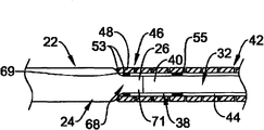
Referring now to Fig. 1, Fig. 1 is the side view of an example embodiment of elongate medical device 10, and elongate medical device 10 is shown as medical guidewire in this embodiment, for example, and endovascular seal wire.Apparatus 10 comprises the slender axles 12 with proximal segment 14 and distal ports 16.Axle 12 can comprise a plurality of structures and/or be made of a plurality of structures, and described a plurality of structure example are as being the proximal structure that extends along proximal segment 14 and/or assembly 18 and the distal structure and/or the assembly 20 that extend along distal ports 16.As will be described in more detail below, thus proximal structure and/or assembly 18 and distal structure and/or assembly 20 are interconnected with one another and form axle 12.
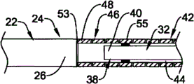
Referring now to Fig. 3, in this embodiment, proximal structure and/or assembly 18 comprise have remote area 24, first (for example, near-end) slender member 22 of distal end 26, proximal end region 28 and proximal end 30.Distal structure and/or assembly 20 can comprise have remote area 34, second (for example, far-end) slender member 32 of distal end 36, proximal end region 38 and proximal end 40.Distal structure and/or assembly 20 can further comprise elongated tubular member 42, and this elongated tubular member 42 limits and runs through chamber 44 wherein and comprise proximal end region 46, proximal end 48, remote area 50 and distal end 52.
Proximal structure and/or assembly 18 and distal structure and/or assembly 20 can for example as interconnect followingly.The proximal end region 46 of tubular element 42 can be attached at for example attachment levels and/or attachment point 53 places the remote area 24 of first (for example, near-end) slender member 22.For example, near the part the part of the distal end 26 of the first slender member 22 or distal end 26 or the distal end 26 is attachable to proximal end 48 or the part of proximal end 48 or near the part the proximal end 48 of elongated tubular member 42.In addition, second or far-end slender member 32 can be arranged in the chamber 44 of tubular element 42, and the proximal end region 38 of the second slender member 32 can be attached at for example attachment levels and/or attachment point 55 places the proximal end region 46 of elongated tubular member 42.For example, near the part the part of the proximal end 40 of the second slender member 32 or proximal end 40 or the proximal end 40 is attachable to proximal end 48 or the part of proximal end 48 or near the part the proximal end 48 of elongated tubular member 42.Can realize attached between tubular element 42 and the first slender member 22 and between tubular element 42 and the second slender member 32 with any technology in multiple attachment techniques and/or the structure and/or structure, will describe in more detail below some examples of attachment techniques and/or structure with reference to accompanying drawing 3-7.
As recognizing, the first slender member 22 and the second slender member 32 all are attached to elongated tubular member 42, and elongated tubular member 42 links together two slender members 22/32.Described link can be implemented as so that the first slender member 22 and the second slender member 32 and elongated tubular member 42 are extended generally along common longitudinal axis.In certain embodiments, as directed, the first slender member 22 and the second slender member 32 are directly not attached, even each other yet not directly contact, but link together by elongated tubular member 42.Like this, in certain embodiments, elongated tubular member 42 can be used as in conjunction with the member of the first slender member 22 and the second slender member 32 with as the structural detail in the distal ports 16 of axle 12---flexible, the property reversed and/or the propelling movement property characteristic of expectation are provided as will be described in more detail below.
The second slender member 32 can extend in the chamber of tubular element 42 44 interior most of length along tubular element 42.For example, in the illustrated embodiment, the second slender member 32 is from its proximal end 40 to the distal end 36 that far extends to it, wherein proximal end 40 is in proximal end region 46 and can approach or the proximal end 48 of adjacent tubular member 42, but distal end 36 distal end 52 of adjacent tubular member 42 also remote area 50 in.Although the second slender member 32 may not extend along the length of tubular element 42 so far away in other embodiments, but at least in certain embodiments, the whole length of the second slender member 32 extensible tubulose members 42 at least about 25% or at least about 50% or at least about 75% or more, perhaps can extend along the substantially whole length of tubular element 42.Yet in other embodiments, the second slender member 32 does not extend along the whole length of tubular element 42, and is stopping before the proximal end 48 of tubular element 42 or before the distal end 52 or before proximal end 48 and distal end 52.
In addition, tubular element 42 and the second slender member 32 be designed and sized to and/or be configured as arrange or otherwise be suitable for and/or be configured so that can be between the inner surface of at least a portion of the outer surface of the second slender member 32 and tubular element 42 restriceted envelope or space 54.For example, tubular element 42 can comprise than the larger internal diameter of external diameter that is arranged on the second slender member 32 wherein.Like this, tubular element 42 can center on the second slender member 32 or its part setting, so that limit space or space 54 between them.In certain embodiments, space or space 54 keep opening wide or keeping not by any other structure filling of apparatus 10 along the substantially whole length (except little attachment point 55) of the second slender member 32.For example, in certain embodiments, space or space 54 can the whole length of slender member 32 approximately 50% or larger, approximately 75% or larger, approximately 90% or larger, approximately 95% or larger scope on extend between the inner surface of the outer surface of the second slender member 32 and tubular element 42 along the length of slender member 32.Yet, in other embodiments, can use other attachment point between slender member 32 and the tubular element 42, can form thus can be by a plurality of spaces or the space of these extra attachment point separations, and in fact these extra attachment point can fill the part in space 54.Still can extend jointly along the most of of length of slender member 32 in these a plurality of spaces or space, for example, and with the percentage ratio extension of as above given total length.Thus, the desired characteristic that tubular element can be used for reinforced shaft 12 for example reverses maybe can push hardness or desired characteristic for example reversed and maybe can push hardness and give axle 12, allows again at least a portion laterally motion in chamber 44 that is centered on by space or space 54 of slender member 32.In another embodiment, one or more other structures, for example, one or more coils, ribbon, band, marking element etc. can be arranged in the space 54 and fill the part in space 54.
Apparatus 10 also can comprise the distal tip 56 that is arranged on its distal end place.Distal tip 56 can comprise any top structure and/or the assembly in multiple top structure and/or the assembly, and can be suitable for and/or be configured to be used to the distal end of apparatus 10 that some characteristic is provided, for example, and noinvasive Flaw characterization or flexible nature.The Performance Characteristics that depends on expectation, distal tip 56 can be formed by multiple different material.In certain embodiments, distal tip 56 can comprise overall or the rounded structure of part, thereby will be arranged on the distal end of axle 12 without (preventing) wound element.In certain embodiments, distal tip 56 can by be easy to weld, soldering or otherwise be attached to axle 12 distal end material for example metal material form soldering.For example, in certain embodiments, distal tip 56 can be solder heads or soldered ball, and it is arranged at the distal end place of apparatus 10 and forms AT rounded part by welding.In other embodiments, distal tip 56 can be the structure of prefabricated or partial precast, and attachment techniques such as the welding that use to be fit to afterwards, soldering, brazing, crimping, frictional fit, glue bond, mechanical interlocked etc. is attached to the distal end of apparatus.Can use various technique such as welding, deep draw, rolling forming or metal stamping, metal injection, casting etc. to form this distal tip structure.
In the embodiment shown in Fig. 1 and Fig. 3, distal tip 56 comprises rounded structure, for example metal or scolder top, it is attached to the distal end 36 of the distal end 52 of tubular element 42 for example and/or the second slender member 32 or the two (as shown) and/or is attached near the distal end of apparatus 10 other structure or other structure at the distal end place of apparatus 10.Thus, in the illustrated embodiment, both extend to and/or extend into distal tip 56 tubular element 42 and the second slender member 32, but as mentioned above, embodiment that may not be all is all like this.In addition, other parts, such as ribbon, coil, indicia band, centering ring etc., the top or the other parts that also can be used as the part of apparatus 10 or be arranged to be close to apparatus 10 are described the example with reference to Fig. 8 below.
Those skilled in the art and other personnel will recognize, material, structure and the size of the first slender member 22 and the second slender member 32 and elongated tubular member 42 mainly determine by the desired characteristic of final seal wire and function, and can use any material, structure and size in large-scale material, structure and the size.
For example, the first slender member 22 and the second slender member 32 and elongated tubular member 42 desired characteristic that can be depending on apparatus 10 is formed by any fit for service material.The example of the material that some are fit to comprises metal, metal alloy, polymer, synthetic etc. or their combination or mixture.The metal that some are fit to and the example of metal alloy comprise: rustless steel, for example 304V, 304L and 316L rustless steel; The alloy that comprises Nitinol, for example Nitinol of linear elasticity or super-elasticity (that is, pseudoelasticity); Nichrome; Nichrome; Cobalt alloy; Tungsten or tungsten alloy; MP35-N (having approximately 35%Ni, 35%Co, 20%Cr, 9.75%Mo, maximum 1%Fe, maximum 1%Ti, maximum 0.25%C, maximum 0.15%Mn and maximum 0.15%Si); Hastelloy; Monel metal 400; Inconel 625 etc.; Perhaps other material that is fit to, or their combination or alloy.In certain embodiments, the metal or metal alloy that is suitable for melts combine technology such as welding, soldering, brazing, crimping, frictional fit, glue bond etc. is used in expectation.Flexible demand or other desired characteristic that also can be based in part on expectation are selected employed concrete material.
Word " Nitinol (nitinol) " is to be created by the seminar of USN's ordnance laboratory (NOL) of the shape-memory properties of at first observing this material.Word " Nitinol " is the acronym of chemical symbol of the chemical symbol that comprises nickel (Ni), titanium (Ti) and the acronym of expression USN's ordnance laboratory (NOL).
Comprise the kind that is denoted as " linear elasticity " in the commercial available nitinol family, although it chemically is being similar to conventional shape memory and super-elasticity (that is, pseudoelasticity) kind, it shows different and useful engineering properties.Use by cold-working industry, direction stress and heat treated technology, make seal wire in the mode that in the stress/strain curves of seal wire, does not represent large " super-elasticity platform " or " decline zone ".Replace, along with recoverable strain increases, stress continues to increase until plastic deformation begins with the relation of generally linear.In certain embodiments, the linear elasticity Nitinol is not for presenting the alloy of analyzing any martensite/austenite phase transformation that can detect by DSC and DMTA on large temperature range.
For example, in certain embodiments, approximately-60 ℃ in about 120 ℃ scope, analyzing the martensite/austenite phase transformation that can detect by DSC and DMTA.Therefore, the mechanical bend characteristic of this material substantially is not subject to cross over the impact of the temperature of this boundless temperature range.In some specific embodiments, alloy is basic identical with the engineering properties under body temperature in the engineering properties under ambient temperature or the indoor temperature.In certain embodiments, the use of linear elasticity Nitinol allows seal wire the representing of the anatomical structure of complications superior " can push performance " everywhere.
In certain embodiments, the nickel percentage by weight arrives in about 60% the scope about 50% in the linear elasticity Nitinol, and residue is mainly titanium.In some special embodiment, the nickel percentage by weight arrives in about 57% the scope about 54% in the synthetic.The example of a suitable Nitinol is can the commercial FHP-NT alloy that obtains from the Furukawa Techno Material Co. of Kanagawa, Japan.The example of the Nitinol that some are fit to comprises that sequence number is 5,238,004 and 6,508, the Nitinol that discloses in 803 the United States Patent (USP), and these two United States Patent (USP)s are incorporated herein by reference.At some among other the embodiment, can with superelastic alloy for example superelastic Nitinol realize the characteristic expected.
In certain embodiments, the first slender member 22 can be made by identical material with the second slender member 32 and elongated tubular member 42, perhaps be made from a variety of materials in certain embodiments, perhaps each in these members all can comprise part or the section that is made from a variety of materials.The material that be used for to consist of the different piece of apparatus 10 may be selected to with the various characteristics flexible and hardness property different piece of giving apparatus 10 for example.
For example, in certain embodiments, first (for example, near-end) slender member 22 can comprise relatively hard material or be formed by relatively hard material, and this relatively hard material for example is the 304v rustless steel seal wire of straightening.Replacedly, slender member 22 can comprise metal or metal alloy or be formed by metal or metal alloy, and described alloy for example is Nitinol, nichrome, nichrome, cobalt alloy or other material that is fit to.In many examples, the material that be used for to consist of first (for example, near-end) slender member 22 may be selected to be relatively firm, for example for propelling movement property and/or the property reversed.
In certain embodiments, second (for example, far-end) slender member 32 can comprise relative flexible material or alternately comprise polymeric material or by relative flexible material or alternately formed by polymeric material, described flexible material for example be super-elasticity (namely, pseudoelasticity) or the linear elasticity alloy (for example, NiTi), described polymeric material for example is high-performance polymer.Alternatively, the second slender member 32 can comprise metal or metal alloy, for example, and rustless steel, nichrome, nichrome, cobalt alloy or other material that is fit to.In many examples, the material that is used for formation second (for example, far-end) slender member 32 may be selected to be the material of relative transversal flexibility, for example for trace ability.
In certain embodiments, elongated tubular member 42 also can comprise relative flexible material or alternately comprise polymeric material or by relative flexible material or alternately formed by polymeric material, described flexible material for example be super-elasticity (namely, pseudoelasticity) or the linear elasticity alloy (for example, NiTi), described polymeric material for example is high-performance polymer.Alternatively, elongated tubular member 42 can comprise metal or metal alloy, for example, and rustless steel, nichrome, nichrome, cobalt alloy or other material that is fit to.In many examples, the material that is used for formation elongated tubular member 42 may be selected to be the material of relative transversal flexibility, for example for trace ability, still also can comprise structure and/or the material that also allows propelling movement property and the property reversed, as will be described in greater detail below.
In some special embodiment, the first slender member 22 is formed by the rustless steel seal wire, and the second slender member 32 is formed by linear elasticity Nitinol seal wire, and elongated tubular member is formed by the superelastic Nitinol pipe.
In some cases, the first slender member 22 or the second slender member 32 or elongated tubular member 42 partly or entirely, perhaps be included in other structures in the apparatus 10 and can be mixed with, apply or be coated with radiopaque material or make or otherwise comprise radiopaque material by radiopaque material.Radiopaque material can be at the material of fluoroscopy screen or the relatively bright image of other perspective display art generation during should being understood to be in medical operating.This relatively bright image helps the user of apparatus 10 to determine the position of apparatus.The example of some radiopaque materials can be including, but not limited to gold, platinum, palladium, tantalum, tungsten alloy, the polymeric material etc. that is doped with the radiopaque implant or their combination or alloy.
In addition, in some cases, can give apparatus 10 MRI (nuclear magnetic resonance) compatibility to a certain degree.For example, be the compatibility of enhancing with nuclear magnetic resonance (MRI) machine, can make in the mode of giving MRI compatibility to a certain degree the other parts of the first slender member 22 and/or the second slender member 32 and/or elongated tubular member 42 or apparatus 10.For example, the first slender member 22 and/or the second slender member 32 and/or elongated tubular member 42 or its part can not made with the material that forms large pseudomorphism (pseudomorphism is the gap in the image) by can seriously not twist image during the MRI perspective display.For example some ferromagnetic material may be unaccommodated, because they can form pseudomorphism in the MRI perspective display.But the first slender member 22 and/or the second slender member 32 and/or elongated tubular member 42 or its part also can be made by the material of MRI machine perspective display.Some materials that represent these characteristics are such as comprising tungsten, Elgiloy (Elgiloy), MP35N, Nitinol etc., and other material, or their combination or alloy.
The length of the first slender member 22 and/or the second slender member 32 and/or elongated tubular member 42 (and/or length of apparatus 10) is usually by useful length desired in the final apparatus and flexible decision.For example, the proximal segment 14 of axle 12 can have in about 20 length in about 300 centimetres or the longer scope, the distal ports 16 of axle 12 can have in about 3 length in about 50 centimetres or the longer scope, and apparatus 10 for example seal wire can have at about 25 total lengths in about 350 centimetres or the longer scope.Can recognize, the adjustable in length of all parts is for so that realize the length of expectation, flexible, the property reversed and other characteristic, and can make amendment to these length in the case of without departing from the spirit of the present invention.
The first slender member 22 and/or the second slender member 32 can have solid section, for example, are solid near-end and far-end core seal wire.Yet in certain embodiments, the first slender member 22 and/or the second slender member 32 can have hollow cross section, perhaps can comprise in other embodiments the conjugate in the zone with solid section and hollow section.In addition, the first slender member 22 and/or the second slender member 32 can comprise circle, flat, ellipse, rectangle, square, polygon etc. or other so various cross-sectional geometry.And cross-sectional geometry can be constant or can change in the length of the first slender member 22 and/or the second slender member 32.For example, Fig. 3 illustrates has substantially the first slender member 22 and/or second slender member 32 of circular section shape, but can recognize, can use in the case of without departing from the spirit of the present invention other cross sectional shape or the combination of these shapes.
In addition, the first slender member 22 and/or the second slender member 32 can comprise one or more bullets or conical region.Conical region can be tapered linearly, be tapered, is tapered equably, anisotropically is tapered or be tapered with step-wise manner with curve mode.The angle of any this bullet all can be according to the change in flexibility of expectation.The length of bullet may be selected to be for large (long length) or less (shorter length) gradual change of obtaining hardness/flexible nature.Can recognize, any part of apparatus 10 and/or the first slender member 22 and/or the second slender member 32 all can be tapered basically, and bullet can be positioned at proximal direction or distal direction.The first slender member 22 and/or the second slender member 32 can comprise that one or more parts and external diameter that external diameter narrows down keep substantially invariable part.Can change number, layout, size and the length of diameter narrowed portion and constant diameter part to realize the characteristic of expectation, for example, flexible and moment of torsion transmission characteristic.For example, among the embodiment shown in Figure 3, the second slender member 32 is larger more flexible than having at proximal end region 38 at remote area 34.Flexible this variation can be by for example along with the second slender member 32 reduces to realize along the area of section of its length to remote extension.Yet, shown in the first slender member 22 have length area of section substantially uniformly along it, and can have thus the length uniform flexible nature substantially along it.In addition, because the structure (for example, the area of section of increase) of the first slender member 22 or because the flexible nature of material therefor type, the first slender member 22 can have all or part of less flexible (harder) than the second slender member 32.Yet, should be realized that, this embodiment provides in the mode of example, and in other embodiments, aforesaid, when wishing, can change the flexible nature of the first slender member 22 and the second slender member 32 by for example using substituting structure and/or material.
In some exemplary embodiments, the external diameter of the first slender member 22 and the second slender member 32 can arrive in about 0.04 inch scope at about 0.005 inch.Yet, should be appreciated that the size that can use in the case of without departing from the spirit of the present invention other.
The external diameter of the first slender member 22 and the second slender member 32, comprise any tapered (taper) and/or constant diameter parts, can be by any technology in the multiple different technologies such as forming by centreless grinding method, process for stamping etc.The centerless grinding technology can use the guidance system that has adopted sensor (for example, optics/reflective sensor, Magnetic Sensor) to avoid the excessive grinding of connecting portion.In addition, centerless grinding technology can use the CBN of good shaping and polishing or diamond abrasive Grinding wheel to avoid the catching structure seal wire during grinding process.In certain embodiments, can use Royal Master HI-AC centerless grinding machine to realize centerless grinding.The example of the method for grinding that some are fit to has obtained disclosure in the U.S. Patent application 10/346,698 (publication number US 2004/0142643) of submitting on January 17th, 2003, this paper is incorporated in this patent application by reference into.
Similarly, in certain embodiments, the part of the first slender member 22 and the second slender member 32 can for example be flat, thereby the flexible nature of expectation is provided, or is provided for the attachment point of other structure.For example, the second slender member 32 can be included in the flat part of its distal end of vicinity 36 in the remote area 34.For example, remote area 34 approximately 0.05 inch can be to about 1 inch distal-most end flat, thereby limit substantially parallel apparent surface, and have at about 0.0005 inch thickness in about 0.003 inch scope.
In addition, the first slender member 22 and the second slender member 32 also can comprise and be configured to and/or be suitable for auxiliary and/or provide member 22/32 and tubular element 42 attached structure.For example, the first slender member 22 and the second slender member 32 can comprise near their end and/or part and/or diameter-increasing portion tapered near the diameter of attachment point and/or that reduce, and be auxiliary attached to be used for.To some exemplary embodiments of these structures be described in more detail with reference to figure 3 to Fig. 7 below.
As mentioned above, tubular element 42 has tubular structure usually, and tubular structure has the tubular wall of cross section hollow, and limits and to run through the chamber 44 of wherein extending, and chamber 44 can be suitable for and/or be configured to be used at least a portion that accommodates or surround the second slender member 32.The concrete cross sectional shape of tubular element 42 can be the shape of any expectation, for example, and circle, ellipse, rectangle, square, polygon etc. or other so various cross-sectional geometry.Described cross-sectional geometry can be constant or can change in tubular element 42 length.For example, Fig. 3 illustrates the tubular element 42 with substantially constant circular section shape, but can recognize, can use in the case of without departing from the spirit of the present invention other cross sectional shape or the combination of these shapes.
In addition, tubular element 42 can comprise the cross section of one or more bullets or conical region and one or more constant diameter, perhaps can roughly comprise constant internal diameter and external diameter.Be tapered and/or constant diameter can show in the variation and/or concordance of size of external diameter, internal diameter and/or wall thickness of tubular element 42.Any tapered zone can be to be tapered linearly, to be tapered, to be tapered equably, anisotropically to be tapered or be tapered with step-wise manner with curve mode.The angle of any this bullet all can change according to the flexible nature of expectation.The length of bullet may be selected to for large (the long length) that realizes hardness/flexible nature or the gradual change of less (shorter length).Describe about slender member 22/32 as top, can recognize, basically any part of apparatus 10 and/or the first slender member 22 and/or the second slender member 32 and/or tubular element 42 all can be tapered or can have constant diameter, and can realize and take office what bullet and/or constant diameter all can extend along proximal direction or distal direction, with realize for example expectation flexible/hardness property.In certain embodiments, tubular element 42 can have the internal diameter that limits chamber 44, described internal diameter size arrives in about 0.06 inch scope at about 0.008 inch, and in certain embodiments, described internal diameter size arrives in about 0.035 inch scope at about 0.02 inch.In addition, in certain embodiments, tubular element 42 can have size at about 0.010 inch external diameter that arrives in about 0.07 inch scope, and in certain embodiments, outside dimension arrives in about 0.04 inch scope at about 0.02 inch.Yet, should be realized that, the size of these and other that this paper provides only provides in the mode of exemplary embodiment, and in other embodiments, the internal diameter of tubular element 42 and the size of external diameter depend on that characteristic and the function of the expectation of apparatus can have a great difference with given size.
A kind of mode of giving extra flexibility is optionally to remove material from the part of tubular element 42.For example, with reference to Fig. 1 and Fig. 3, tubular element 42 can comprise the thin-walled tubular structure, the thin-walled tubular structure be included in form in the part of tubular element 42 or along one or more apertures 60 that the whole length of tubular element 42 forms, such as groove, otch, seam, groove etc.Aperture 60 can form so that one or more ridge teat or stringer 70 are formed in the tubular element 42.These ridge teats or stringer 70 (Fig. 2) can be included in tubular element 42 bodies residual fraction that forms tubular element 42 after the aperture 60, and because aperture 60 and can be used for the torsional stiffness that keeps relatively high in the transversal flexibility that keeps aspiration level.This structure may be expected, because it can allow tubular element 42 or its part to have the transversal flexibility of aspiration level, and has the ability that moment of torsion and propulsive force is delivered to remote area 50 from proximal end region 46.Can basically form in any known fashion aperture 60.For example, can by cut such as miniature machined, sawing, cut, grinding, mill, casting, molded, chemical etching or processing or other known method such as method form aperture 60.In some such embodiment, by cutting and/or the part of removing pipe forming aperture 60, thereby form the structure of stiffener 60.
In certain embodiments, aperture 60 is the body wall of penetrating tubular member 42 fully, so that be communicated with via aperture 60 fluid between the outside of chamber 44 and tubular element 42.In certain embodiments, aperture 60 can only partly extend in the body wall of tubular element 42 on the inner surface of tubular element 42 or outer surface.Some other embodiment can comprise aperture 60 fully and the combinations of part by the both of these case of tubular element 42 body walls.The shape and size in aperture 60 for example can change to realize the characteristic expected.For example, the shape in aperture 60 can change to consist essentially of any suitable shape, such as square, circle, rectangle, ball shape, ellipse, polygon, elongated shape, irregularly shaped, spiral type (pitch can change or can not change) or other mode that is fit to etc., and can comprise circle or square edge, and length and width etc. are variable.
In certain embodiments, some adjacent apertures 60 can form so that they comprise part around the mutual crossover of circumference of tubular element 42.In other embodiments, some adjacent apertures 60 can be arranged so that their mutually crossovers, but arrange in the mode of transversal flexibility that aspiration level is provided.In addition, aperture 60 can be arranged or around the circumference of tubular element 42, to realize the characteristic of expectation along the length of tubular element 42.For example, aperture 60 can symmetrical mode be arranged, basically be arranged on equably opposite side or along the length of tubular element 42 interval equably such as the circumference around tubular element 42, perhaps aperture 60 can density mode cumulative or decrescence arrange, and perhaps can asymmetrical or irregular mode arrange.
As can recognizing, the interval in aperture 60, layout and/or the directed relevant ridge teat that maybe can form or the interval in the stringer, layout and/or directedly can change to realize the characteristic expected.For example, according to the characteristic of expectation, can change or as one man change according to staged along number, (relative to each other) nearness, density, size, shape and/or the degree of depth in the aperture 60 of tubular element 42 length.For example, at the end place near tubular element 42, the number in aperture 60 or proximity to one another can be large, and at the other end place near tubular element 42, number or the proximity to one another in aperture 60 can be relatively little, and vice versa.For example, in certain embodiments, the remote area 50 of tubular element 42 can comprise the aperture 60 of greater density, and the proximal end region 46 of tubular element 42 can comprise the aperture of less density, perhaps can in addition without any aperture 60.Thus, remote area 50 can have greatly transversal flexibility with respect to proximal end region 46.Should be realized that, also can be used to realize flexible difference along the expectation of tubular element length along the similar variation of size, shape and/or the degree of depth in the aperture 60 on tubular element 42 length.
In the embodiment shown in Fig. 1 and Fig. 2, aperture 60 and the ridge teat that is associated or stringer 70 are with the length setting of substantially uniform mode along tubular element 42.In this embodiment, aperture 60 has length and width, and the length in aperture is extended perpendicular to the longitudinal axis of tubular element 42 substantially.In other words, aperture 60 can have the main shaft that extends along their length, and the length in hole is radially extended about the longitudinal axis of body 42, and the main shaft cardinal principle is perpendicular to the longitudinal axis of tubular body 42.
In addition, in the illustrated embodiment, to be formed on two be in one group a plurality of groups, wherein in aperture 60, each length along tubular element 42 in two apertures 60 in the group is arranged on similar lengthwise position place, but on the opposite side of circumference at tubular element of tubular element.For example, aperture 60a and 60b (Fig. 2) form a pair of, and this is arranged on the lengthwise position place to the length along tubular element, and Y-Y is formed on the opposite side of tubular element along the line, and its center line Y-Y is basically perpendicular to the axis of tubular element.Aperture 60c and aperture 60a and 60b longitudinal subdivision are shown open, and be basically perpendicular to the longitudinal axis (the pairing aperture 60d of not shown aperture 60c is because aperture 60d is positioned on the opposite side of tubular element) of tubular element.Yet, should be realized that, in other embodiments, can change the arrangement in hole to realize the desired characteristic along tubular element 42 length.For example, can only single hole or plural hole be set at some point along apparatus length, rather than pair of holes.In addition, the main shaft in hole can be along different angle settings, and needn't be perpendicular to the longitudinal axis of tubular element 42.
In a word, show can be in the situation that do not depart from the variation that scope of the present invention changes structure, number and the layout in aperture 60 for these figure and these descriptions.Be that 6,428,489 United States Patent (USP) and sequence number are to have disclosed in 6,579,246 the United States Patent (USP) to be formed at some additional examples that the hole such as otch or groove in the tubular body is arranged in sequence number, these two United States Patent (USP)s are incorporated herein by reference.Similarly, the serial number of submitting on February 28th, 2003 is 10/375, disclosed some additional examples that are formed on for the layout of the otch of the tubular body of medical apparatus and instruments or groove in 493 the U.S. Patent application, this U.S. Patent application is incorporated herein by reference.
The flexible nature of tubular element 42 also can be by realizing with other method, for example, assigns to realize by the particular portion that material and/or one or more stiffener is appended to tubular element 42.
As mentioned above, can utilize any attachment techniques in various attachment techniques and/or the structure and/or structure to realize attached between tubular element 42 and the first slender member 22 and between tubular element 42 and the second slender member 32, perhaps realize attached between any structure of existence in the apparatus 10.The example of the attachment techniques that some are fit to comprises welding, soldering, brazing, crimping, frictional fit, glue bond, mechanical interlocked etc.
Some examples that can be suitable for the welding procedure of some embodiment comprise laser weld, resistance welded, TIG welding (Tungsten-arc Inert-Gas welding), little Plasma Welding, electron beam welding, friction welding, inertia production weld etc.The laser welding apparatus that can be suitable for some application can be from the Unitek Miyachi in Monrovia, California and commercial acquisition of Rofin-Sinar company of Plymouth, the state of Michigan.The resistance welding equipment that can be suitable for some application can be from the Palomar Products company of Carlsbad, California and commercial acquisition of Polaris Electronics in Aura west, the Kansas State.The TIG welding equipment that can be suitable for some application can obtain from the Weldlogic company in Niu Baili park, California is commercial.Little Plasma Welding equipment that can be suitable for some application can obtain from the Process Welding Systems company of Tennessee State Smyrna is commercial.
In certain embodiments, laser or little Plasma Welding can be used to realize attached.In laser weld, light beam is used for supplying with necessary heat.Laser weld can be conducive to the technique that the present invention conceives, because the use of laser thermal source can provide significant precision.It should further be appreciated that, this laser weld also can be used for other parts of attached apparatus.In addition, in certain embodiments, laser energy can be used as the thermal source of soldering, brazing etc., so that different parts or the structure of seal wire is attached together.Again, the thermal source that laser is used as this interconnection technique can be favourable, because the use of laser thermal source can provide sufficient precision.An instantiation of this technology comprises the laser diode soldering.
In addition, at some in other the exemplary embodiment, can by utilize mechanical fastener or body and/or by inflatable alloy for example bismuth alloy realize and/or be auxiliary attached.The U.S. Patent application 10/375 of submitting on February 26th, 2003, disclosed some examples of the method, technology and the structure that can be used for the different piece by using this expandable material interconnection seal wire among 766 (the publication number US 2004/0167441), this U.S. Patent application is incorporated herein by reference.Be 6 in sequence number, 918, disclosed certain methods and structure for the different section that interconnects in the U.S. Patent application 10/086,992 (publication number US 2003/0069521) that 882 United States Patent (USP) and on February 28th, 2002 submit to, these two parts of files are incorporated herein by reference.
Referring now to Fig. 3, Fig. 3 illustrates an example of attached structure.In this arrangement, the distal end 26 of first (for example, near-end) slender member 22 has the bullet that extends to reduced part 68, and can form half hourglass shape shape.Reduced part 68 comprises the constant diameter part 71 of tapered part 69 and reduced.This structure on the distal end 24 can be convenient to the distal end 26 of the first slender member 22 accurately is placed in the chamber 44 of slender member, because the structure of reduced part 68 trends towards making slender member 22 44 interior placed in the middle in the chamber.The constant diameter part 71 of dwindling extends in the chamber 44, and can use above-mentioned any method for example along the diameter parts 71 that dwindles attachment points/regional 53 places realize attached.And, second (for example, far-end) slender member 32 can be arranged in the chamber 44 of tubular element 42, and can use above-mentioned any method the proximal end region 38 of slender member 32 to be attached to the proximal end region 46 of elongated tubular member 42 at for example attachment points 55 places.At some among other the embodiment, also can utilize along the extra attachment points length of the second slender member 32, between tubular element 42 and the second slender member 32.In certain embodiments, attachment part can center on the whole circumferential extension of the longitudinal axis of apparatus 10, for example, and around the whole circumferential extension of the first slender member 22 and the second slender member 32.Yet, among other the embodiment, the attachment points/zone at one or more intervals can be set around the circumference of longitudinal axis at some.The use of some attachment techniques such as laser weld or laser diode soldering etc. only can be conducive to connect around the part of circumference, because these methods are easy to realize carrying out the required precision of this connection.As mentioned above, in this embodiment, between the proximal end 40 of the distal end 26 of the first slender member 22 and the second slender member 32, do not contact yet and directly do not link.Yet, in substituting embodiment, between these two members, can contact and even form direct link.
For example, referring now to Fig. 4, it illustrates similar to the embodiment shown in Fig. 3 in many aspects embodiment, and wherein identical Reference numeral represents similar structure.Yet, in Fig. 4, exist between the distal end 26 of the first slender member 22 and the proximal end 40 of the second slender member 32 to contact.These two structure fabrics are set to so that they abut against each other flushes, but directly do not link between these two structures.Yet, in substituting embodiment, between these two members, can have all any attachment techniques described above of use and form direct link.
Referring now to Fig. 5, it illustrates in many aspects in the above and with reference to Fig. 3 and Fig. 4 another embodiment similar with the embodiment that describes is shown, and wherein identical Reference numeral represents similar structure.Yet in this embodiment, the distal end 26 of first (for example, near-end) slender member 22 do not comprise reduced part and do not extend in the chamber 44, but forms the junction surface that flushes with the proximal end 48 of tubular element.Above-mentioned any attachment techniques all can be used to form this junction surface.
Referring now to Fig. 6, it illustrates in many aspects to top another embodiment similar with the embodiment that describes is shown, and wherein identical Reference numeral represents similar structure.Yet, in this embodiment, be different from as shown in Figure 3 and Figure 4 the reduced part 68 with the extension that comprises constant diameter part 71 or as shown in Figure 5 flush the junction surface, first (for example, near-end) distal end 30 of slender member 22 comprises taper (tapered) part 70 that only slightly extends in the chamber 44, and attachment points/zone 53 arranges along tapered part 70.Again, can use above-mentioned any attachment techniques.
Referring now to Fig. 7, it illustrates in many aspects to top another embodiment similar with the embodiment that describes is shown; Wherein identical Reference numeral represents similar structure.Yet in this embodiment, the distal end 30 of first (for example, near-end) slender member 22 does not comprise the reduced part, but the proximal end 48 of tubular element comprises expanded region 80, so that comprise the internal diameter of increase along the chamber 44 of expanded region 80.Thus, the distal end 26 of the first slender member 22 may extend in the chamber 44 of the expansion that is limited by expanded region 80, and can carry out at for example attachment points 53 places attached between two structures.Again, can use above-mentioned any attachment techniques.
Referring now to Fig. 8, it illustrates the sectional view such as the distal end of another exemplary embodiment of the apparatus 110 of seal wire etc., and apparatus 110 can comprise the structure similar to said structure, and wherein identical Reference numeral represents similar structure.Yet in this embodiment, apparatus 110 comprises some extra/substituting structures in its distal portions.For example, do not extend to distal tip although apparatus for example comprises the distal end 36 of distal tip 56, the second (for example, far-end) slender member 32 as described above, but terminate in the position at adjacent distal end top 56.Tubular element 42 extends and is attached to distal tip 56.This embodiment also comprises structure 180, for example, and the ribbon of shaping or silk etc.Structure 180 comprises the proximal end 181 of the distal end 36 that is attached to the second slender member 32, and to remote extension, and the distal end 183 with distal tip of being attached to 56.Structure 180 can be made by various materials, comprises metal, alloy, plastics or other material that is fit to, for example, and material mentioned above.The cross section of structure 180 can be various shapes, comprises circle, ellipse, pancake, band shape, rectangle, square or any shape that other is fit to or their combination.
Top structure also can comprise elongated flexure member 190, for example, spiral winding or polymeric jacket, it is arranged in the chamber 44 of tubular element 42 and around at least a portion setting of at least a portion and/or the structure 180 of the second slender member 32.In the illustrated embodiment, flexure member 190 is spiral winding.This coil 190 can be used for strengthening the distal tip of apparatus, and/or can be used as radiopaque labelling piece, or as the two.This coil can by silk or ribbon form or comprise the silk or ribbon, this or ribbon can have solid section and can comprise any shape in the various cross sectional shapes, comprise circle, ellipse, pancake, band shape or any shape that other is fit to or their combination.Coil 190 can be made by various materials, comprises metal, alloy, plastics or other material that is fit to, and comprises radiopaque material, has described hereinbefore many materials wherein.At United States Patent (USP) 6,918, disclosed the spendable top structure that other is fit to and some examples of structure in the U.S. Patent application 10/086,992 (publication number US 2003/0069521) that on February 28th, 882 and 2002 submitted to, these two parts of files are incorporated herein by reference.
It will also be appreciated that apparatus 10 110 or other can comprise supernumerary structure, for example, extra shaping silk or electric fuse or ribbon, indicating strip and/or coil, extra interior loop or exterior loop, inner sleeve or overcoat or coating etc.Such as common general knowledge, those skilled in the art and other staff will recognize how these supernumerary structures are incorporated in the apparatus.
In addition, in certain embodiments, can with coating for example the coating of smooth (for example hydrophilic) or other type be applied to above-mentioned medical apparatus and instruments or structure partly or entirely on.For example, this coating can be applied on a part or whole part of apparatus 10 or 110, comprise for example other parts of apparatus section 14/16, the first slender member 22 and the second slender member 32, tubular element 42, distal tip 56 or apparatus 10 or 110.Hydrophobic coating such as fluoropolymer, silicones etc. provides the dry lubricity that improves seal wire operation and apparatus replacing.Smooth coating is improved maneuverability and is improved damage ride-through capability (lesion crossing capability).The smooth polymer that is fit to is known in the art, and can comprise hydrophilic polymer, for example, polyarylene oxide compound (polyaryleneoxides), polyvinylpyrrolidone (polyvinylpyrolidones), polyvinyl alcohol, hydroxy alkyl cellulose, alginic acid, saccharide, caprolactone etc. and their mixture and compositions.Hydrophilic polymer can be blended among them or be mixed in the water-fast chemical compound of formula ratio (comprising some polymer) and form the coating with suitable lubricity, caking property and solubility.Can be 6,139,510 and 5,772 in sequence number, some other the example that finds this coating in 609 the United States Patent (USP) and be used to form the materials and methods of this coating, this United States Patent (USP) is incorporated this paper by reference into.In certain embodiments, the part far away of seal wire scribbles aforesaid hydrophilic polymer, and nearer part scribbles fluoropolymer, for example, and politef (PTFE).
In certain embodiments, the use of coating can be given the flexible of axle 12 expectations.Can be according to the selected coating material of characteristic changing of expectation.For example, having the coating of low flintiness or soft may be very little on the total flexible impact of apparatus 10.On the contrary, the coating that has a high rigidity may make axle become harder and/or make the flexible variation of axle.
The present invention should not be considered as being confined to above-mentioned instantiation, covers all aspects of the present invention that suitably limit in the claims and be construed as.The technical staff who the present invention relates to the field will be readily understood that after reading this description and can be applicable to various modification of the present invention, equivalent processes and many structures.Should be realized that, the disclosure only is exemplary in many aspects.Can be in the situation that do not exceed the scope of the invention to details, especially making amendment aspect shape, size and the procedure.Certainly, scope of the present invention is limited by the spoken and written languages of statement claims.
Claims (21)
1. medical apparatus and instruments in the body comprises:
The first slender member with proximal end region, remote area and distal end; The proximal end region of the first slender member has the circular cross-section that limits external diameter;
Elongated tubular member, described elongated tubular member comprises metal material and limits the chamber of running through wherein, described elongated tubular member has proximal end region, proximal end, remote area and distal end, the described proximal end region of described elongated tubular member is attached to the described remote area of described the first slender member in the first attachment levels, the far-end of described elongated tubular member from the near-end of elongated tubular member to elongated tubular member extends along distal direction and leave the first slender member;
Described elongated tubular member has the circular cross-section that limits external diameter;
The external diameter equal in length of the external diameter of described elongated tubular member and the first slender member;
And
The second slender member, described the second slender member has proximal end region, proximal end, remote area and distal end, described the second slender member is arranged in the described intracavity of described elongated tubular member, and the outer surface of the described proximal end region of described the second slender member is attached to the inner surface of the described proximal end region of described elongated tubular member in the second attachment levels.
2. medical apparatus and instruments in the body according to claim 1, it is characterized in that, described the first slender member and described the second slender member are mutually directly not attached, and/or the distal end of the proximal end of wherein said the second slender member and described the first slender member is spaced apart.
3. medical apparatus and instruments in the body according to claim 1 is characterized in that, the proximal end of described the second slender member contacts with the distal end of described the first slender member.
4. medical apparatus and instruments in each described body in 3 according to claim 1, it is characterized in that, the described distal end of described the first slender member is attached to described tubular element, and/or the described proximal end of wherein said tubular element is attached to described the first slender member.
5. medical apparatus and instruments in each described body in 3 according to claim 1, it is characterized in that, described elongated tubular member is to remote extension, so that at least a portion of the described remote area of described elongated tubular member is arranged to contiguous or away from the described remote area of described the second slender member.
6. medical apparatus and instruments in each described body in 3 according to claim 1, it is characterized in that, also comprise distal tip, and wherein said elongated tubular member is opened to the position of contiguous described distal tip to remote extension and is attached to described distal tip, and/or wherein said the second slender member to remote extension to the position that is close to described distal tip and be attached to described distal tip.
7. medical apparatus and instruments in each described body in 3 according to claim 1, it is characterized in that, described elongated tubular member has length, and described the second slender member extends at the described intracavity of described elongated tubular member along at least 50% length of described elongated tubular member, and/or the described distal end of wherein said the first slender member extends in the described chamber of described elongated tubular member.
8. medical apparatus and instruments in each described body in 3 according to claim 1, it is characterized in that, at least a portion of the described remote area of described the first slender member is taper, and/or wherein said the second slender member comprises bullet, and/or at least a portion of the described proximal end region of wherein said elongated tubular member is taper.
9. medical apparatus and instruments in each described body in 3 according to claim 1 is characterized in that, described the first slender member has solid section, and described the second slender member has solid section.
10. medical apparatus and instruments in each described body in 3 according to claim 1 is characterized in that, described elongated tubular member comprises and limits a plurality of otch of being formed on wherein or the tubular wall of groove.
11. medical apparatus and instruments in the body according to claim 10, it is characterized in that, described tubular element is Axis Extension longitudinally, and described otch or groove comprise the length of extending about described longitudinal axis, and the length orientation of described otch or groove becomes to be basically perpendicular to described longitudinal axis.
12. medical apparatus and instruments in the body according to claim 11, it is characterized in that, it is in one group a plurality of groups that described otch or groove are formed on two, and be limited at along the cardinal principle corresponding position of the length of described elongated tubular member, and wherein two otch or the groove in each group is positioned on the opposite side of described elongated tubular member, and/or wherein otch or the groove of each group are arranged to be in respect to contiguous group around axis 90 degree rotations place.
13. medical apparatus and instruments in the body according to claim 10 is characterized in that, the otch of the per unit length of described elongated tubular member or the density of groove increase, and/or the degree of depth of described otch or groove or size increase at distal direction along described elongated tubular member.
14. medical apparatus and instruments in each described body in 3 is characterized in that according to claim 1, described the first slender member comprises the first metal material, and described the second slender member comprises the second metal material that is different from described the first metal material.
15. medical apparatus and instruments in each described body in 3 is characterized in that according to claim 1, described the second slender member and/or described elongated tubular member comprise Nitinol.
16. medical apparatus and instruments in each described body in 3 according to claim 1, it is characterized in that, medical apparatus and instruments comprises seal wire in the described body, described the first slender member comprises the near-end core component, described the second slender member comprises the far-end core component, and described elongated tubular member comprise the remote area of the described near-end core component that interconnects and described far-end core component proximal end region and about the remote area of described far-end core component also to the structure of remote extension.
17. a method of making medical apparatus and instruments in the body, described method comprises:
Provide have proximal end region, the first slender member of remote area and distal end; The proximal end region of the first slender member has the circular cross-section that limits external diameter;
Elongated tubular member is provided, and described elongated tubular member comprises that metal material and restriction run through chamber wherein, and described elongated tubular member has proximal end region, proximal end, remote area and distal end;
Described elongated tubular member has the circular cross-section that limits external diameter;
The external diameter equal in length of the proximal end region of the external diameter of described elongated tubular member and the first slender member;
Provide have proximal end region, the second slender member of proximal end, remote area and distal end;
Described the second slender member is arranged in the described intracavity of described elongated tubular member;
The outer surface of the described proximal end region of described the second slender member is attached to the inner surface of the described proximal end region of described elongated tubular member; And
The described proximal end region of described elongated tubular member is attached to the described remote area of described the first slender member, leaves the first slender member so that the remote area of described elongated tubular member from the proximal end region of elongated tubular member to elongated tubular member extends along distal direction.
18. method according to claim 17, it is characterized in that, by welding, glue bond or mechanical interlocked, the described proximal end region of described the second slender member is attached to the described proximal end region of described elongated tubular member, and/or the described proximal end region of described elongated tubular member is attached to the described remote area of described the first slender member.
19. according to claim 17 or 18 described methods, it is characterized in that, also comprise distal tip being provided and described distal tip being attached to described elongated tubular member or described distal tip is attached to described the second slender member.
20. according to claim 17 or 18 described methods, it is characterized in that, medical apparatus and instruments comprises seal wire in the described body, described the first slender member comprises the near-end core component, described the second slender member comprises the far-end core component, and described elongated tubular member comprise the remote area of the described near-end core component that interconnects and described far-end core component proximal end region and about the remote area of described far-end core component also to the structure of remote extension.
21. method according to claim 18 is characterized in that, described welding is soldering.
Applications Claiming Priority (3)
| Application Number | Priority Date | Filing Date | Title |
|---|---|---|---|
| US11/833,117 US8409114B2 (en) | 2007-08-02 | 2007-08-02 | Composite elongate medical device including distal tubular member |
| US11/833117 | 2007-08-02 | ||
| PCT/US2008/071787 WO2009018457A2 (en) | 2007-08-02 | 2008-07-31 | Composite elongate medical device including distal tubular member |
Publications (2)
| Publication Number | Publication Date |
|---|---|
| CN101815553A CN101815553A (en) | 2010-08-25 |
| CN101815553B true CN101815553B (en) | 2013-04-24 |
Family
ID=40305278
Family Applications (1)
| Application Number | Title | Priority Date | Filing Date |
|---|---|---|---|
| CN2008801098033A Expired - Fee Related CN101815553B (en) | 2007-08-02 | 2008-07-31 | Composite elongate medical device including distal tubular member |
Country Status (6)
| Country | Link |
|---|---|
| US (1) | US8409114B2 (en) |
| EP (1) | EP2183013B1 (en) |
| JP (1) | JP5642544B2 (en) |
| CN (1) | CN101815553B (en) |
| CA (1) | CA2695370C (en) |
| WO (1) | WO2009018457A2 (en) |
Families Citing this family (60)
| Publication number | Priority date | Publication date | Assignee | Title |
|---|---|---|---|---|
| US9034007B2 (en) | 2007-09-21 | 2015-05-19 | Insera Therapeutics, Inc. | Distal embolic protection devices with a variable thickness microguidewire and methods for their use |
| US11406791B2 (en) | 2009-04-03 | 2022-08-09 | Scientia Vascular, Inc. | Micro-fabricated guidewire devices having varying diameters |
| EP2370237B1 (en) | 2008-12-08 | 2015-12-02 | Jeff Christian | Micro-cutting machine for forming cuts in products |
| US10363389B2 (en) | 2009-04-03 | 2019-07-30 | Scientia Vascular, Llc | Micro-fabricated guidewire devices having varying diameters |
| GB0902339D0 (en) * | 2009-02-12 | 2009-04-01 | St Georges Healthcare Nhs Trus | Percutaneous guidewire |
| US9950137B2 (en) | 2009-04-03 | 2018-04-24 | Scientia Vascular, Llc | Micro-fabricated guidewire devices formed with hybrid materials |
| US9795765B2 (en) * | 2010-04-09 | 2017-10-24 | St. Jude Medical International Holding S.À R.L. | Variable stiffness steering mechanism for catheters |
| AU2011269729B2 (en) | 2010-06-23 | 2016-12-08 | Monash University | Constrained immunogenic compositions and uses therefor |
| US8684953B2 (en) * | 2012-05-13 | 2014-04-01 | Ozca Engineering Solutions Ltd. | Steering tool |
| US10639099B2 (en) * | 2012-05-25 | 2020-05-05 | Biosense Webster (Israel), Ltd. | Catheter having a distal section with spring sections for biased deflection |
| DE102012010687B4 (en) | 2012-05-30 | 2021-08-19 | ADMEDES GmbH | A method for producing a body implant, an assembly comprising a guide wire and a body implant, and a medical instrument |
| US9504476B2 (en) | 2012-10-01 | 2016-11-29 | Microvention, Inc. | Catheter markers |
| CN103961785A (en) * | 2013-01-31 | 2014-08-06 | 朝日英达科株式会社 | Slitted pipe and guide wire using the same |
| US9848882B2 (en) * | 2013-03-08 | 2017-12-26 | Scientia Vascular, Llc | Micro-fabricated embolic devices |
| US8715315B1 (en) | 2013-03-15 | 2014-05-06 | Insera Therapeutics, Inc. | Vascular treatment systems |
| US8679150B1 (en) | 2013-03-15 | 2014-03-25 | Insera Therapeutics, Inc. | Shape-set textile structure based mechanical thrombectomy methods |
| US8715314B1 (en) | 2013-03-15 | 2014-05-06 | Insera Therapeutics, Inc. | Vascular treatment measurement methods |
| EP3620203A1 (en) | 2013-03-15 | 2020-03-11 | Insera Therapeutics, Inc. | Vascular treatment devices |
| EP3024381B1 (en) * | 2013-07-26 | 2019-06-19 | Boston Scientific Scimed, Inc. | Ffr sensor head design that minimizes stress induced pressure offsets |
| US20150045695A1 (en) * | 2013-08-06 | 2015-02-12 | Abbott Cardiovascular Systems, Inc. | Guide wire with core made from low-modulus cobalt-chromium alloy |
| WO2015137098A1 (en) * | 2014-03-14 | 2015-09-17 | テルモ株式会社 | Medical tube |
| US11020017B2 (en) * | 2015-02-16 | 2021-06-01 | Biosense Webster (Israel) Ltd. | Angioplasty guidewire |
| WO2016136767A1 (en) * | 2015-02-24 | 2016-09-01 | 株式会社グッドマン | Catheter and method for producing catheter |
| US10173033B2 (en) * | 2015-04-16 | 2019-01-08 | Baylis Medical Company Inc. | Imaging marker |
| US10327933B2 (en) | 2015-04-28 | 2019-06-25 | Cook Medical Technologies Llc | Medical cannulae, delivery systems and methods |
| US10675057B2 (en) | 2015-04-28 | 2020-06-09 | Cook Medical Technologies Llc | Variable stiffness cannulae and associated delivery systems and methods |
| US9768664B2 (en) | 2015-05-21 | 2017-09-19 | The Boeing Company | Balanced eccentric gear design and method |
| US10203022B2 (en) | 2015-11-04 | 2019-02-12 | The Boeing Company | Elliptically interfacing wobble motion gearing system and method |
| US10024391B2 (en) | 2016-01-06 | 2018-07-17 | The Boeing Company | Elliptically interfacing gearbox |
| CN108697423A (en) | 2016-02-16 | 2018-10-23 | 伊瑟拉医疗公司 | The part flow arrangement of suction unit and anchoring |
| US10574109B2 (en) | 2016-04-28 | 2020-02-25 | The Boeing Company | Permanent magnet biased virtual elliptical motor |
| US10555756B2 (en) | 2016-06-27 | 2020-02-11 | Cook Medical Technologies Llc | Medical devices having coaxial cannulae |
| US11207502B2 (en) | 2016-07-18 | 2021-12-28 | Scientia Vascular, Llc | Guidewire devices having shapeable tips and bypass cuts |
| US11052228B2 (en) | 2016-07-18 | 2021-07-06 | Scientia Vascular, Llc | Guidewire devices having shapeable tips and bypass cuts |
| US10821268B2 (en) | 2016-09-14 | 2020-11-03 | Scientia Vascular, Llc | Integrated coil vascular devices |
| US11026716B2 (en) | 2016-11-22 | 2021-06-08 | Boston Scientific Scimed, Inc. | Medical device shaft resistant to compression and/or tension |
| US11452541B2 (en) | 2016-12-22 | 2022-09-27 | Scientia Vascular, Inc. | Intravascular device having a selectively deflectable tip |
| US10215244B2 (en) | 2017-03-02 | 2019-02-26 | The Boeing Company | Elliptically interfacing gear assisted braking system |
| EP3595595A1 (en) | 2017-03-14 | 2020-01-22 | Boston Scientific Scimed, Inc. | Medical device shaft including a liner |
| CN110621263B (en) | 2017-03-14 | 2021-10-22 | 波士顿科学国际有限公司 | Medical device with internal components |
| US10520063B2 (en) | 2017-04-21 | 2019-12-31 | The Boeing Company | Mechanical virtual elliptical drive |
| US10267383B2 (en) | 2017-05-03 | 2019-04-23 | The Boeing Company | Self-aligning virtual elliptical drive |
| JP6884884B2 (en) | 2017-05-03 | 2021-06-09 | ボストン サイエンティフィック サイムド,インコーポレイテッドBoston Scientific Scimed,Inc. | Medical device with sealing assembly |
| ES2966345T3 (en) | 2017-05-26 | 2024-04-22 | Scientia Vascular Inc | Microfabricated medical device with a non-helical cutting arrangement |
| EP3630258B1 (en) * | 2017-05-26 | 2024-03-20 | Scientia Vascular, Inc. | Core-wire joint with micro-fabricated medical devices |
| EP3717922A2 (en) | 2017-12-03 | 2020-10-07 | Cook Medical Technologies, LLC | Mri compatible interventional wireguide |
| US10456556B2 (en) * | 2018-02-19 | 2019-10-29 | Bendit Technologies Ltd. | Steering tool with enhanced flexibility and trackability |
| US11305095B2 (en) | 2018-02-22 | 2022-04-19 | Scientia Vascular, Llc | Microfabricated catheter having an intermediate preferred bending section |
| US11419721B2 (en) | 2018-04-26 | 2022-08-23 | Boston Scientific Scimed, Inc. | Medical device with coupling member |
| EP3784177A1 (en) | 2018-04-26 | 2021-03-03 | Boston Scientific Scimed, Inc. | Motorized telescoping medical device delivery system |
| JP7059399B2 (en) | 2018-04-26 | 2022-04-25 | ボストン サイエンティフィック サイムド,インコーポレイテッド | Medical device with nested seal assembly |
| EP3943141A3 (en) * | 2018-09-10 | 2022-03-02 | Orbusneich Medical Pte. Ltd | Variable flexibility catheter support frame |
| US10968969B2 (en) | 2019-03-18 | 2021-04-06 | The Boeing Company | Nutational braking systems and methods |
| EP3958944A1 (en) * | 2019-04-24 | 2022-03-02 | Ecole Polytechnique Federale De Lausanne (Epfl) | Enhanced torque steerable guidewire |
| CN112107391A (en) * | 2019-06-21 | 2020-12-22 | 乐普(北京)医疗器械股份有限公司 | Loading sheath and conveying system |
| US11723767B2 (en) | 2019-08-15 | 2023-08-15 | Boston Scientific Scimed, Inc. | Medical device including attachable tip member |
| US11471650B2 (en) | 2019-09-20 | 2022-10-18 | Biosense Webster (Israel) Ltd. | Mechanism for manipulating a puller wire |
| US11459098B2 (en) | 2019-11-27 | 2022-10-04 | The Boeing Company | Variable speed transmission and related methods |
| US11944758B2 (en) * | 2019-12-16 | 2024-04-02 | Acclarent, Inc. | Atraumatic tip assembly for guidewire |
| JP2023180260A (en) * | 2020-11-12 | 2023-12-21 | テルモ株式会社 | guide wire |
Citations (1)
| Publication number | Priority date | Publication date | Assignee | Title |
|---|---|---|---|---|
| US5437288A (en) * | 1992-09-04 | 1995-08-01 | Mayo Foundation For Medical Education And Research | Flexible catheter guidewire |
Family Cites Families (341)
| Publication number | Priority date | Publication date | Assignee | Title |
|---|---|---|---|---|
| US1553227A (en) | 1924-09-18 | 1925-09-08 | Paragon Button Corp | Slicing machine |
| US1866888A (en) | 1931-03-11 | 1932-07-12 | Master Woodworker Mfg Co | Sawing machine |
| US2275827A (en) * | 1940-07-02 | 1942-03-10 | Belmont Radio Corp | Electric motor |
| US2441166A (en) | 1942-03-27 | 1948-05-11 | Raspet August | Helical spring |
| US2413805A (en) * | 1943-08-17 | 1947-01-07 | Theodore W Vickers | Electrical machine |
| US2561890A (en) | 1945-07-25 | 1951-07-24 | George C Stoddard | Dynamoelectric machine |
| US2722614A (en) | 1951-08-11 | 1955-11-01 | Gulton Mfg Co | Vibration and shock-responsive device |
| US2857536A (en) | 1955-07-18 | 1958-10-21 | Edward C Light | Variable reluctance machine |
| US2864017A (en) | 1955-11-28 | 1958-12-09 | Waltscheff Dimo Dimitroff | Inducto-motive power apparatus with a plurality of rotors |
| US2871793A (en) * | 1956-06-29 | 1959-02-03 | Robbins & Myers | Electric motor and pump combination |
| US3249776A (en) | 1962-06-13 | 1966-05-03 | Bendix Corp | Nutation motor |
| US3294994A (en) | 1963-05-10 | 1966-12-27 | Bendix Corp | Nutation motor or generator |
| US3363470A (en) * | 1964-07-20 | 1968-01-16 | Raphael O. Yavne | Accelerometer |
| US3334253A (en) | 1966-04-25 | 1967-08-01 | Francis A Hill | Magnet traction motors |
| US3452740A (en) | 1966-05-31 | 1969-07-01 | Us Catheter & Instr Corp | Spring guide manipulator |
| US3452227A (en) | 1966-10-21 | 1969-06-24 | Elvin C Welch | Motor with gyrating rotor |
| GB1169984A (en) | 1967-01-25 | 1969-11-12 | Nat Res Dev | Improvements relating to Dynamo Electric Machines |
| US3463953A (en) | 1967-03-20 | 1969-08-26 | Gilbert A Maxwell | Resonant motor |
| US3512019A (en) | 1968-02-21 | 1970-05-12 | Systems Technology Inc | Electromagnetic device |
| US3625200A (en) | 1969-08-26 | 1971-12-07 | Us Catheter & Instr Corp | Controlled curvable tip member |
| US3686990A (en) | 1970-03-05 | 1972-08-29 | Geometron Co Inc | Cutting elongated stock |
| SU712908A1 (en) | 1973-07-16 | 1980-01-30 | Amdurov Aleksandr E | End-face wave-type electric motor |
| US3841308A (en) | 1973-10-15 | 1974-10-15 | Medical Evaluation Devices & I | Distally valved catheter device |
| US3890977A (en) | 1974-03-01 | 1975-06-24 | Bruce C Wilson | Kinetic memory electrodes, catheters and cannulae |
| CS171544B1 (en) | 1974-09-03 | 1976-10-29 | ||
| US3906938A (en) | 1974-09-03 | 1975-09-23 | Lake Region Manufacturing Comp | Coil spring wire guide |
| US4003369A (en) * | 1975-04-22 | 1977-01-18 | Medrad, Inc. | Angiographic guidewire with safety core wire |
| US4020829A (en) | 1975-10-23 | 1977-05-03 | Willson James K V | Spring guide wire with torque control for catheterization of blood vessels and method of using same |
| US4000672A (en) * | 1976-02-26 | 1977-01-04 | Altair National Corporation | Slitting machine for corrugated pipe |
| US4142119A (en) * | 1977-03-21 | 1979-02-27 | The United States Of America As Represented By The Administrator Of The National Aeronautics And Space Administration | Rotary electric device |
| SU758421A1 (en) | 1978-05-04 | 1980-08-23 | Московский Ордена Ленина Авиационный Институт Им.Серго Орджоникидзе | Motor-vibrator with rolling rotor |
| US4215703A (en) | 1978-08-29 | 1980-08-05 | Willson James K V | Variable stiffness guide wire |
| US4330725A (en) | 1980-03-10 | 1982-05-18 | Morgan Actuators, Inc. | Nutating motor coupling |
| DE3029907A1 (en) | 1980-08-07 | 1982-03-18 | Hoechst Ag, 6000 Frankfurt | CONTINUOUS METHOD AND DEVICE FOR PRODUCING A VINYL CHLORIDE POLYMERISATE IN AQUEOUS SUSPENSION |
| EP0069522A1 (en) | 1981-06-26 | 1983-01-12 | Research Machines Plc | Educational aid for teaching computer programming |
| US4425919A (en) * | 1981-07-27 | 1984-01-17 | Raychem Corporation | Torque transmitting catheter apparatus |
| FR2515859A1 (en) | 1981-10-29 | 1983-05-06 | Crouzet Sa | ELECTROMAGNETIC CYLINDER DEBRAYABLE |
| US4476754A (en) | 1981-12-07 | 1984-10-16 | Ducret Lucien C | Automatic cable measuring and cutting machine |
| AU550184B2 (en) | 1982-02-26 | 1986-03-06 | Unilever Plc | Pack for detergent powder |
| US4545390A (en) | 1982-09-22 | 1985-10-08 | C. R. Bard, Inc. | Steerable guide wire for balloon dilatation procedure |
| DE3245958A1 (en) | 1982-12-11 | 1984-06-14 | Battelle-Institut E.V., 6000 Frankfurt | LASER ARRANGEMENT |
| US4563181A (en) * | 1983-02-18 | 1986-01-07 | Mallinckrodt, Inc. | Fused flexible tip catheter |
| FR2541775B1 (en) * | 1983-02-28 | 1985-10-04 | Onera (Off Nat Aerospatiale) | ELECTROSTATIC SUSPENSION ACCELEROMETERS |
| US4774949A (en) | 1983-06-14 | 1988-10-04 | Fogarty Thomas J | Deflector guiding catheter |
| US4665906A (en) | 1983-10-14 | 1987-05-19 | Raychem Corporation | Medical devices incorporating sim alloy elements |
| US4574670A (en) * | 1983-11-17 | 1986-03-11 | Lockheed Corporation | Multiple angle cutting apparatus |
| US5135531A (en) | 1984-05-14 | 1992-08-04 | Surgical Systems & Instruments, Inc. | Guided atherectomy system |
| US4781186A (en) | 1984-05-30 | 1988-11-01 | Devices For Vascular Intervention, Inc. | Atherectomy device having a flexible housing |
| US4786220A (en) | 1984-06-18 | 1988-11-22 | Borg-Warner Corporation | Cutting tool wear monitor |
| US4580551A (en) * | 1984-11-02 | 1986-04-08 | Warner-Lambert Technologies, Inc. | Flexible plastic tube for endoscopes and the like |
| JPS61110198A (en) | 1984-11-05 | 1986-05-28 | 株式会社東芝 | Matrix type display unit |
| US5470330A (en) | 1984-12-07 | 1995-11-28 | Advanced Interventional Systems, Inc. | Guidance and delivery system for high-energy pulsed laser light |
| DE3447642C1 (en) * | 1984-12-28 | 1986-09-18 | Bernhard M. Dr. 5600 Wuppertal Cramer | Steerable guidewire for catheters |
| JPH025799Y2 (en) * | 1986-02-07 | 1990-02-13 | ||
| US4721117A (en) * | 1986-04-25 | 1988-01-26 | Advanced Cardiovascular Systems, Inc. | Torsionally stabilized guide wire with outer jacket |
| US4676249A (en) | 1986-05-19 | 1987-06-30 | Cordis Corporation | Multi-mode guidewire |
| US4867173A (en) | 1986-06-30 | 1989-09-19 | Meadox Surgimed A/S | Steerable guidewire |
| US4922777A (en) | 1986-09-05 | 1990-05-08 | Contour Saws, Inc. | Band saw for cutting shaped pieces of bar stock |
| DE3633691C1 (en) | 1986-10-03 | 1987-07-23 | Keuro Maschb Gmbh & Co Kg | Device for feeding rod-shaped workpiece material in a cutting machine |
| US4790331A (en) | 1986-12-02 | 1988-12-13 | Sherwood Medical Company | Method for placement of catheter in a blood vessel |
| US4763647A (en) | 1987-01-06 | 1988-08-16 | C. R. Bard, Inc. | Dual coil steerable guidewire |
| JPH0685927B2 (en) | 1987-01-30 | 1994-11-02 | 株式会社エフイ−シ− | Drive device for vertical axis rolling mill |
| US5250069A (en) | 1987-02-27 | 1993-10-05 | Terumo Kabushiki Kaisha | Catheter equipped with expansible member and production method thereof |
| US4811743A (en) * | 1987-04-21 | 1989-03-14 | Cordis Corporation | Catheter guidewire |
| US5211183A (en) | 1987-05-13 | 1993-05-18 | Wilson Bruce C | Steerable memory alloy guide wires |
| US4989608A (en) * | 1987-07-02 | 1991-02-05 | Ratner Adam V | Device construction and method facilitating magnetic resonance imaging of foreign objects in a body |
| SU1529365A1 (en) | 1987-08-13 | 1989-12-15 | Всесоюзный научно-исследовательский институт электромеханики | Stepping electric motor with rolling rotor |
| US4875489A (en) | 1987-08-14 | 1989-10-24 | Advanced Cardiovascular Systems, Inc. | Extendable guidewire |
| US5181668A (en) * | 1987-09-07 | 1993-01-26 | Osaka Gas Co., Ltd. | Apparatus for running a wire through a pipe |
| US4846193A (en) | 1987-09-21 | 1989-07-11 | Advanced Cardiovascular Systems, Inc. | Extendable guide wire for vascular procedures |
| US4953553A (en) | 1989-05-11 | 1990-09-04 | Advanced Cardiovascular Systems, Inc. | Pressure monitoring guidewire with a flexible distal portion |
| US4964409A (en) | 1989-05-11 | 1990-10-23 | Advanced Cardiovascular Systems, Inc. | Flexible hollow guiding member with means for fluid communication therethrough |
| US5050606A (en) | 1987-09-30 | 1991-09-24 | Advanced Cardiovascular Systems, Inc. | Method for measuring pressure within a patient's coronary artery |
| US5273042A (en) | 1987-10-28 | 1993-12-28 | Medical Parameters, Inc. | Guidewire advancement method |
| US4934380A (en) | 1987-11-27 | 1990-06-19 | Boston Scientific Corporation | Medical guidewire |
| US4832047A (en) | 1987-12-15 | 1989-05-23 | Target Therapeutics | Guide wire device |
| US5009137A (en) * | 1987-12-18 | 1991-04-23 | Pitney Bowes Inc. | Cutter module for a modular mailing machine |
| US4827941A (en) | 1987-12-23 | 1989-05-09 | Advanced Cardiovascular Systems, Inc. | Extendable guidewire for cardiovascular procedures |
| US4846186A (en) | 1988-01-12 | 1989-07-11 | Cordis Corporation | Flexible guidewire |
| DE3801514A1 (en) | 1988-01-20 | 1989-08-03 | Schmidt Feinmech | ACCELERATION SENSOR AND METHOD FOR THE PRODUCTION THEREOF |
| DE3903133A1 (en) | 1988-02-04 | 1989-08-31 | Amada Co | WORKPIECE WORKABILITY DETECTION METHOD AND METHOD FOR MACHINING A WORKPIECE BY MEANS OF A CHIP MACHINING MACHINE USING THIS METHOD |
| JP2895463B2 (en) * | 1988-04-05 | 1999-05-24 | テルモ株式会社 | Guide wire for catheter |
| US4884579A (en) | 1988-04-18 | 1989-12-05 | Target Therapeutics | Catheter guide wire |
| US4935017A (en) | 1988-04-29 | 1990-06-19 | C. R. Bard, Inc. | Variable shaped catheter system and method for catheterization |
| US4998923A (en) * | 1988-08-11 | 1991-03-12 | Advanced Cardiovascular Systems, Inc. | Steerable dilatation catheter |
| US4917102A (en) * | 1988-09-14 | 1990-04-17 | Advanced Cardiovascular Systems, Inc. | Guidewire assembly with steerable adjustable tip |
| US4950257A (en) * | 1988-09-15 | 1990-08-21 | Mallinckrodt, Inc. | Catheter introducer with flexible tip |
| US4922164A (en) | 1988-10-03 | 1990-05-01 | Sarcos Group | Eccentric motion motor |
| US4994069A (en) * | 1988-11-02 | 1991-02-19 | Target Therapeutics | Vaso-occlusion coil and method |
| US5507751A (en) * | 1988-11-09 | 1996-04-16 | Cook Pacemaker Corporation | Locally flexible dilator sheath |
| US5065769A (en) | 1988-11-23 | 1991-11-19 | Boston Scientific Corporation | Small diameter guidewires of multi-filar, cross-wound coils |
| US4985022A (en) * | 1988-11-23 | 1991-01-15 | Med Institute, Inc. | Catheter having durable and flexible segments |
| US4932959A (en) | 1988-12-01 | 1990-06-12 | Advanced Cardiovascular Systems, Inc. | Vascular catheter with releasably secured guidewire |
| DE8900077U1 (en) | 1989-01-04 | 1990-05-17 | Baker, Susan, London, Gb | |
| US5007434A (en) * | 1989-02-07 | 1991-04-16 | Advanced Cardiovascular Systems, Inc. | Catheter tip attitude controlling guide wire |
| US4966163A (en) | 1989-02-14 | 1990-10-30 | Advanced Cardiovascular Systems, Inc. | Extendable guidewire for vascular procedures |
| US5052404A (en) | 1989-03-02 | 1991-10-01 | The Microspring Company, Inc. | Torque transmitter |
| US4911148A (en) * | 1989-03-14 | 1990-03-27 | Intramed Laboratories, Inc. | Deflectable-end endoscope with detachable flexible shaft assembly |
| US4960410A (en) | 1989-03-31 | 1990-10-02 | Cordis Corporation | Flexible tubular member for catheter construction |
| DE69016905T2 (en) | 1989-04-13 | 1995-06-08 | Mitsubishi Cable Ind Ltd | CATHETER. |
| US5063935A (en) | 1989-04-27 | 1991-11-12 | C. R. Bard, Inc. | Catheter guidewire with varying radiopacity |
| US4955384A (en) | 1989-05-11 | 1990-09-11 | Advanced Cardiovascular Systems, Inc. | Guiding member for vascular catheters with a flexible link distal section |
| US4955862A (en) | 1989-05-22 | 1990-09-11 | Target Therapeutics, Inc. | Catheter and catheter/guide wire device |
| US4954022A (en) | 1989-06-16 | 1990-09-04 | Underwood Mold Co., Inc. | Method for machining multiple cuts in a workpiece to a uniform depth |
| US4968306A (en) | 1989-07-07 | 1990-11-06 | Advanced Cardiovascular Systems, Inc. | Intravascular catheter having an adjustable length infusion section to delivery therapeutic fluid |
| US5144959A (en) | 1989-08-15 | 1992-09-08 | C. R. Bard, Inc. | Catheter guidewire with varying radiopacity |
| US5318529A (en) | 1989-09-06 | 1994-06-07 | Boston Scientific Corporation | Angioplasty balloon catheter and adaptor |
| US5256144A (en) | 1989-11-02 | 1993-10-26 | Danforth Biomedical, Inc. | Low profile, high performance interventional catheters |
| US5095915A (en) * | 1990-03-19 | 1992-03-17 | Target Therapeutics | Guidewire with flexible distal tip |
| US4990143A (en) * | 1990-04-09 | 1991-02-05 | Sheridan Catheter Corporation | Reinforced medico-surgical tubes |
| US5109830A (en) | 1990-04-10 | 1992-05-05 | Candela Laser Corporation | Apparatus for navigation of body cavities |
| US5238004A (en) | 1990-04-10 | 1993-08-24 | Boston Scientific Corporation | High elongation linear elastic guidewire |
| US5059177A (en) | 1990-04-19 | 1991-10-22 | Cordis Corporation | Triple lumen balloon catheter |
| US5147317A (en) | 1990-06-04 | 1992-09-15 | C.R. Bard, Inc. | Low friction varied radiopacity guidewire |
| USRE37148E1 (en) * | 1990-06-04 | 2001-04-24 | Medtronic Ave, Inc. | Guidewire tip construction |
| US5040543A (en) | 1990-07-25 | 1991-08-20 | C. R. Bard, Inc. | Movable core guidewire |
| US5217482A (en) | 1990-08-28 | 1993-06-08 | Scimed Life Systems, Inc. | Balloon catheter with distal guide wire lumen |
| US5345945A (en) | 1990-08-29 | 1994-09-13 | Baxter International Inc. | Dual coil guidewire with radiopaque distal tip |
| US5125395A (en) | 1990-09-12 | 1992-06-30 | Adair Edwin Lloyd | Deflectable sheath for optical catheter |
| US5267979A (en) | 1990-09-17 | 1993-12-07 | E-Z-Em, Inc. | Pressure responsive valve catheter |
| US5341818A (en) | 1992-12-22 | 1994-08-30 | Advanced Cardiovascular Systems, Inc. | Guidewire with superelastic distal portion |
| US6165292A (en) | 1990-12-18 | 2000-12-26 | Advanced Cardiovascular Systems, Inc. | Superelastic guiding member |
| EP0491349B1 (en) | 1990-12-18 | 1998-03-18 | Advanced Cardiovascular Systems, Inc. | Method of manufacturing a Superelastic guiding member |
| US5106455A (en) * | 1991-01-28 | 1992-04-21 | Sarcos Group | Method and apparatus for fabrication of micro-structures using non-planar, exposure beam lithography |
| US5329923A (en) | 1991-02-15 | 1994-07-19 | Lundquist Ingemar H | Torquable catheter |
| US5454787A (en) | 1991-02-15 | 1995-10-03 | Lundquist; Ingemar H. | Torquable tubular assembly and torquable catheter utilizing the same |
| US5228441A (en) | 1991-02-15 | 1993-07-20 | Lundquist Ingemar H | Torquable catheter and method |
| US5231989A (en) | 1991-02-15 | 1993-08-03 | Raychem Corporation | Steerable cannula |
| AU660444B2 (en) | 1991-02-15 | 1995-06-29 | Ingemar H. Lundquist | Torquable catheter and method |
| US5315996A (en) | 1991-02-15 | 1994-05-31 | Lundquist Ingemar H | Torquable catheter and method |
| US5254107A (en) | 1991-03-06 | 1993-10-19 | Cordis Corporation | Catheter having extended braid reinforced transitional tip |
| EP0508414B1 (en) | 1991-04-09 | 1996-07-24 | The Furukawa Electric Co., Ltd. | Joined parts of Ni-Ti alloys with different metals and joining method therefor |
| DK0585359T3 (en) | 1991-05-07 | 1998-05-11 | Target Therapeutics Inc | The catheter guidewire |
| US5354623A (en) | 1991-05-21 | 1994-10-11 | Cook Incorporated | Joint, a laminate, and a method of preparing a nickel-titanium alloy member surface for bonding to another layer of metal |
| US5242759A (en) | 1991-05-21 | 1993-09-07 | Cook Incorporated | Joint, a laminate, and a method of preparing a nickel-titanium alloy member surface for bonding to another layer of metal |
| US5769830A (en) | 1991-06-28 | 1998-06-23 | Cook Incorporated | Soft tip guiding catheter |
| US5304131A (en) * | 1991-07-15 | 1994-04-19 | Paskar Larry D | Catheter |
| CA2073750C (en) * | 1991-07-18 | 1996-11-12 | Toshiaki Yutori | Catheter guide wire and catheter |
| CA2114010A1 (en) * | 1991-07-24 | 1993-02-04 | Motasim M. Sirhan | Low profile perfusion-type dilatation catheter |
| US5630806A (en) | 1991-08-13 | 1997-05-20 | Hudson International Conductors | Spiral wrapped medical tubing |
| CA2117088A1 (en) | 1991-09-05 | 1993-03-18 | David R. Holmes | Flexible tubular device for use in medical applications |
| US5741429A (en) * | 1991-09-05 | 1998-04-21 | Cardia Catheter Company | Flexible tubular device for use in medical applications |
| US5308435A (en) | 1991-10-07 | 1994-05-03 | Home Fashions, Inc. | Method and apparatus for fabricating honeycomb insulating material |
| US5605162A (en) * | 1991-10-15 | 1997-02-25 | Advanced Cardiovascular Systems, Inc. | Method for using a variable stiffness guidewire |
| US5376084A (en) | 1991-10-17 | 1994-12-27 | Imagyn Medical, Inc. | Catheter with internal mandrel and method |
| US5333620A (en) | 1991-10-30 | 1994-08-02 | C. R. Bard, Inc. | High performance plastic coated medical guidewire |
| US5205830A (en) * | 1991-11-12 | 1993-04-27 | Arrow International Investment Corporation | Catheter assembly |
| US5243996A (en) | 1992-01-03 | 1993-09-14 | Cook, Incorporated | Small-diameter superelastic wire guide |
| WO1993013704A1 (en) | 1992-01-09 | 1993-07-22 | Endomedix Corporation | Bi-directional miniscope |
| US5284128A (en) * | 1992-01-24 | 1994-02-08 | Applied Medical Resources Corporation | Surgical manipulator |
| JP3151927B2 (en) | 1992-04-10 | 2001-04-03 | 株式会社村田製作所 | Acceleration sensor |
| US5254106A (en) | 1992-04-17 | 1993-10-19 | Feaster Fred T | Hydrodissection needle |
| US5259393A (en) | 1992-05-13 | 1993-11-09 | Cordis Corporation | Guidewire having controlled radiopacity tip |
| US5315906A (en) | 1992-05-15 | 1994-05-31 | Vought Aircraft Company | Automated extrusion processing machine |
| US5584821A (en) | 1992-06-02 | 1996-12-17 | E-Z-Em, Inc. | Soft tip catheter |
| EP0597195B1 (en) | 1992-08-18 | 1999-07-21 | The Spectranetics Corporation | Fiber optic guide wire |
| US5257974A (en) | 1992-08-19 | 1993-11-02 | Scimed Life Systems, Inc. | Performance enhancement adaptor for intravascular balloon catheter |
| US5334145A (en) | 1992-09-16 | 1994-08-02 | Lundquist Ingemar H | Torquable catheter |
| US5441483A (en) | 1992-11-16 | 1995-08-15 | Avitall; Boaz | Catheter deflection control |
| US5439000A (en) | 1992-11-18 | 1995-08-08 | Spectrascience, Inc. | Method of diagnosing tissue with guidewire |
| US5476701A (en) | 1992-12-20 | 1995-12-19 | Berger; David | Table pad construction |
| US5368564A (en) | 1992-12-23 | 1994-11-29 | Angeion Corporation | Steerable catheter |
| JPH06202361A (en) | 1992-12-28 | 1994-07-22 | Fuji Xerox Co Ltd | Electrophotographic sensitive body and its production |
| US5669926A (en) | 1993-01-25 | 1997-09-23 | Aust & Taylor Medical Corporation | Surgical instrument |
| JP3345147B2 (en) * | 1993-01-26 | 2002-11-18 | テルモ株式会社 | Vasodilators and catheters |
| DE69432379T2 (en) | 1993-01-26 | 2004-02-05 | Terumo K.K. | Vascular dilatation device and catheter |
| ES2157226T3 (en) * | 1993-01-28 | 2001-08-16 | Angiomed Ag | GUIDE PIECE OF A PIECE AND PROCEDURE FOR MANUFACTURING. |
| US5358493A (en) | 1993-02-18 | 1994-10-25 | Scimed Life Systems, Inc. | Vascular access catheter and methods for manufacture thereof |
| US5336205A (en) | 1993-02-25 | 1994-08-09 | Target Therapeutics, Inc. | Flow directed catheter |
| US5365943A (en) | 1993-03-12 | 1994-11-22 | C. R. Bard, Inc. | Anatomically matched steerable PTCA guidewire |
| US5772609A (en) | 1993-05-11 | 1998-06-30 | Target Therapeutics, Inc. | Guidewire with variable flexibility due to polymeric coatings |
| JP3383009B2 (en) | 1993-06-29 | 2003-03-04 | テルモ株式会社 | Vascular catheter |
| US5562619A (en) | 1993-08-19 | 1996-10-08 | Boston Scientific Corporation | Deflectable catheter |
| NL9301642A (en) | 1993-09-22 | 1995-04-18 | Cordis Europ | Microcatheter. |
| US5601539A (en) * | 1993-11-03 | 1997-02-11 | Cordis Corporation | Microbore catheter having kink-resistant metallic tubing |
| US5720300A (en) * | 1993-11-10 | 1998-02-24 | C. R. Bard, Inc. | High performance wires for use in medical devices and alloys therefor |
| JPH07185009A (en) * | 1993-11-11 | 1995-07-25 | Mayo Found For Medical Education & Res | Flexible guide wire for catheter |
| JPH09507399A (en) | 1993-11-12 | 1997-07-29 | マイクロ インターベンショナル システムズ | Catheter with small diameter and high torque |
| US5507301A (en) * | 1993-11-19 | 1996-04-16 | Advanced Cardiovascular Systems, Inc. | Catheter and guidewire system with flexible distal portions |
| US5807075A (en) | 1993-11-23 | 1998-09-15 | Sarcos, Inc. | Disposable ambulatory microprocessor controlled volumetric pump |
| US5520194A (en) | 1993-12-07 | 1996-05-28 | Asahi Intecc Co., Ltd. | Guide wire for medical purpose and manufacturing process of coil thereof |
| JPH07178176A (en) | 1993-12-24 | 1995-07-18 | Terumo Corp | Catheter |
| JP3725900B2 (en) * | 1994-01-14 | 2005-12-14 | アドヴァンスト・カーディオヴァスキュラー・システムズ・インコーポレイテッド | Guide wire with superelastic distal portion |
| US5571073A (en) | 1994-01-28 | 1996-11-05 | Cordis Corporation | Catheter flexible tip assembly |
| US5911715A (en) | 1994-02-14 | 1999-06-15 | Scimed Life Systems, Inc. | Guide catheter having selected flexural modulus segments |
| US5569218A (en) | 1994-02-14 | 1996-10-29 | Scimed Life Systems, Inc. | Elastic guide catheter transition element |
| US5902290A (en) | 1994-03-14 | 1999-05-11 | Advanced Cardiovascular Systems, Inc. | Catheter providing intraluminal access |
| US5546958A (en) | 1994-03-31 | 1996-08-20 | Lake Region Manufacturing Company, Inc. | Guidewire extension system with tactile connection indication |
| US5406960A (en) * | 1994-04-13 | 1995-04-18 | Cordis Corporation | Guidewire with integral core and marker bands |
| US5533985A (en) | 1994-04-20 | 1996-07-09 | Wang; James C. | Tubing |
| US5656011A (en) | 1994-04-28 | 1997-08-12 | Epflex Feinwerktechnik Gmbh | Endoscope tube system |
| US6139510A (en) | 1994-05-11 | 2000-10-31 | Target Therapeutics Inc. | Super elastic alloy guidewire |
| US5666969A (en) | 1994-05-18 | 1997-09-16 | Scimed Life Systems, Inc. | Guidewire having multiple radioscopic coils |
| JP3970341B2 (en) | 1994-06-20 | 2007-09-05 | テルモ株式会社 | Vascular catheter |
| US5460187A (en) | 1994-07-01 | 1995-10-24 | Boston Scientific Corp. | Fluoroscopically viewable guidewire |
| US5496294A (en) * | 1994-07-08 | 1996-03-05 | Target Therapeutics, Inc. | Catheter with kink-resistant distal tip |
| US5497785A (en) * | 1994-07-27 | 1996-03-12 | Cordis Corporation | Catheter advancing guidewire and method for making same |
| WO1996009848A1 (en) | 1994-09-26 | 1996-04-04 | Medtronic, Inc. | Cathether flexible distal tip |
| US5599305A (en) * | 1994-10-24 | 1997-02-04 | Cardiovascular Concepts, Inc. | Large-diameter introducer sheath having hemostasis valve and removable steering mechanism |
| US5520645A (en) | 1994-10-28 | 1996-05-28 | Intelliwire, Inc. | Low profile angioplasty catheter and/or guide wire and method |
| US5658264A (en) | 1994-11-10 | 1997-08-19 | Target Therapeutics, Inc. | High performance spiral-wound catheter |
| CA2205666A1 (en) * | 1994-11-23 | 1996-05-30 | Micro Interventional Systems, Inc. | High torque balloon catheter |
| US5622184A (en) * | 1994-11-29 | 1997-04-22 | Applied Medical Resources Corporation | Guidewire and method of manufacture |
| US5599326A (en) * | 1994-12-20 | 1997-02-04 | Target Therapeutics, Inc. | Catheter with multi-layer section |
| US5569197A (en) | 1994-12-21 | 1996-10-29 | Schneider (Usa) Inc | Drug delivery guidewire |
| US5810885A (en) | 1994-12-28 | 1998-09-22 | Omrix Biopharm Sa | Device for applying one or several fluids |
| AU4605896A (en) | 1995-01-04 | 1996-07-24 | Medtronic, Inc. | Improved method of soft tip forming |
| US5797856A (en) | 1995-01-05 | 1998-08-25 | Cardiometrics, Inc. | Intravascular guide wire and method |
| US5666968A (en) | 1995-03-17 | 1997-09-16 | Intelliwire, Inc. | Flexible guide wire with extension capability and guide wire extension for use therewith |
| US5916178A (en) | 1995-03-30 | 1999-06-29 | Medtronic, Inc. | Steerable high support guidewire with thin wall nitinol tube |
| US6325790B1 (en) | 1995-04-11 | 2001-12-04 | Cordis Corporation | Soft tip catheter |
| EP0738495B1 (en) | 1995-04-18 | 2002-06-26 | Schneider (Europe) GmbH | Pressure measuring guide wire |
| US5551444A (en) | 1995-05-31 | 1996-09-03 | Radius Medical Technologies, Inc. | Flexible guidewire with radiopaque outer coil and non-radiopaque inner coil |
| US6273404B1 (en) | 1995-06-05 | 2001-08-14 | Scimed Life Systems, Inc. | Method of making monolithic hub and strain relief |
| US5788707A (en) | 1995-06-07 | 1998-08-04 | Scimed Life Systems, Inc. | Pull back sleeve system with compression resistant inner shaft |
| EP0755693A1 (en) | 1995-07-18 | 1997-01-29 | Schneider (Europe) Ag | Catheter guide wire |
| US5746701A (en) | 1995-09-14 | 1998-05-05 | Medtronic, Inc. | Guidewire with non-tapered tip |
| US6027461A (en) * | 1995-10-11 | 2000-02-22 | Micro Therapeutics, Inc. | Infusion guidewire having fixed core wire and flexible radiopaque marker |
| US5843050A (en) | 1995-11-13 | 1998-12-01 | Micro Therapeutics, Inc. | Microcatheter |
| US5868685A (en) * | 1995-11-14 | 1999-02-09 | Devices For Vascular Intervention | Articulated guidewire |
| US5833632A (en) | 1995-12-07 | 1998-11-10 | Sarcos, Inc. | Hollow guide wire apparatus catheters |
| US6428489B1 (en) | 1995-12-07 | 2002-08-06 | Precision Vascular Systems, Inc. | Guidewire system |
| US5931830A (en) | 1995-12-07 | 1999-08-03 | Sarcos L.C. | Hollow coil guide wire apparatus for catheters |
| US20030069522A1 (en) | 1995-12-07 | 2003-04-10 | Jacobsen Stephen J. | Slotted medical device |
| CA2192045A1 (en) | 1995-12-07 | 1997-06-08 | Stephen C. Jacobsen | Catheter guide wire apparatus |
| US5813996A (en) | 1995-12-21 | 1998-09-29 | Scimed Life Systems, Inc. | Guide wire extension system with magnetic coupling |
| US6004279A (en) | 1996-01-16 | 1999-12-21 | Boston Scientific Corporation | Medical guidewire |
| US5807249A (en) | 1996-02-16 | 1998-09-15 | Medtronic, Inc. | Reduced stiffness, bidirectionally deflecting catheter assembly |
| JP3255271B2 (en) * | 1996-03-12 | 2002-02-12 | ダイワ精工株式会社 | Spinning reel for fishing |
| US5891056A (en) | 1996-03-15 | 1999-04-06 | Advanced Cardiovascular Systems, Inc. | Guidewire replacement device with flexible intermediate section |
| US5788653A (en) | 1996-04-03 | 1998-08-04 | Cordis Corporation | Guidewire extension with sliding release mechanism |
| US5682894A (en) | 1996-04-26 | 1997-11-04 | Orr; Gregory C. | Guide wire |
| US6488637B1 (en) | 1996-04-30 | 2002-12-03 | Target Therapeutics, Inc. | Composite endovascular guidewire |
| US5836926A (en) | 1996-05-13 | 1998-11-17 | Schneider (Usa) Inc | Intravascular catheter |
| US6068623A (en) * | 1997-03-06 | 2000-05-30 | Percusurge, Inc. | Hollow medical wires and methods of constructing same |
| US6017319A (en) * | 1996-05-24 | 2000-01-25 | Precision Vascular Systems, Inc. | Hybrid tubular guide wire for catheters |
| US5690120A (en) | 1996-05-24 | 1997-11-25 | Sarcos, Inc. | Hybrid catheter guide wire apparatus |
| US5916194A (en) | 1996-05-24 | 1999-06-29 | Sarcos, Inc. | Catheter/guide wire steering apparatus and method |
| US6440088B1 (en) | 1996-05-24 | 2002-08-27 | Precision Vascular Systems, Inc. | Hybrid catheter guide wire apparatus and method |
| US5782811A (en) * | 1996-05-30 | 1998-07-21 | Target Therapeutics, Inc. | Kink-resistant braided catheter with distal side holes |
| US5843244A (en) | 1996-06-13 | 1998-12-01 | Nitinol Devices And Components | Shape memory alloy treatment |
| US5827242A (en) | 1996-06-21 | 1998-10-27 | Medtronic, Inc. | Reinforced catheter body and method for its fabrication |
| US5676697A (en) | 1996-07-29 | 1997-10-14 | Cardiovascular Dynamics, Inc. | Two-piece, bifurcated intraluminal graft for repair of aneurysm |
| US5902254A (en) | 1996-07-29 | 1999-05-11 | The Nemours Foundation | Cathether guidewire |
| US6553880B2 (en) * | 1996-09-16 | 2003-04-29 | Sarcos, Lc | Micromachining system |
| US6014919A (en) | 1996-09-16 | 2000-01-18 | Precision Vascular Systems, Inc. | Method and apparatus for forming cuts in catheters, guidewires, and the like |
| US5971975A (en) | 1996-10-09 | 1999-10-26 | Target Therapeutics, Inc. | Guide catheter with enhanced guidewire tracking |
| US6001068A (en) | 1996-10-22 | 1999-12-14 | Terumo Kabushiki Kaisha | Guide wire having tubular connector with helical slits |
| GB9623402D0 (en) * | 1996-11-08 | 1997-01-08 | Smiths Industries Plc | Catheter assemblies and inner cannulae |
| US5904657A (en) | 1997-02-26 | 1999-05-18 | Unsworth; John D. | System for guiding devices in body lumens |
| US5911717A (en) | 1997-03-17 | 1999-06-15 | Precision Vascular Systems, Inc. | Catheter deliverable thrombogenic apparatus and method |
| US5800454A (en) | 1997-03-17 | 1998-09-01 | Sarcos, Inc. | Catheter deliverable coiled wire thromboginic apparatus and method |
| US5906618A (en) | 1997-03-20 | 1999-05-25 | Vanderbilt University | Microcatheter with auxiliary parachute guide structure |
| US6042553A (en) * | 1997-04-15 | 2000-03-28 | Symbiosis Corporation | Linear elastic member |
| US5895378A (en) * | 1997-05-29 | 1999-04-20 | Target Therapeutics, Inc. | Flow-directed catheter having multiple tapers and radio-opaque markers |
| EP0988081A1 (en) | 1997-06-04 | 2000-03-29 | Advanced Cardiovascular Systems, Inc. | Steerable guidewire with enhanced distal support |
| US5951539A (en) | 1997-06-10 | 1999-09-14 | Target Therpeutics, Inc. | Optimized high performance multiple coil spiral-wound vascular catheter |
| US5947940A (en) | 1997-06-23 | 1999-09-07 | Beisel; Robert F. | Catheter reinforced to prevent luminal collapse and tensile failure thereof |
| US5980471A (en) | 1997-10-10 | 1999-11-09 | Advanced Cardiovascular System, Inc. | Guidewire with tubular connector |
| US6056702A (en) | 1998-10-02 | 2000-05-02 | Cordis Corporation | Guidewire with outer sheath |
| US5935108A (en) | 1997-11-14 | 1999-08-10 | Reflow, Inc. | Recanalization apparatus and devices for use therein and method |
| US6106485A (en) | 1997-11-18 | 2000-08-22 | Advanced Cardivascular Systems, Inc. | Guidewire with shaped intermediate portion |
| US6273876B1 (en) | 1997-12-05 | 2001-08-14 | Intratherapeutics, Inc. | Catheter segments having circumferential supports with axial projection |
| US6251092B1 (en) | 1997-12-30 | 2001-06-26 | Medtronic, Inc. | Deflectable guiding catheter |
| US6063200A (en) | 1998-02-10 | 2000-05-16 | Sarcos L.C. | Three-dimensional micro fabrication device for filamentary substrates |
| US6346091B1 (en) * | 1998-02-13 | 2002-02-12 | Stephen C. Jacobsen | Detachable coil for aneurysm therapy |
| US6022369A (en) | 1998-02-13 | 2000-02-08 | Precision Vascular Systems, Inc. | Wire device with detachable end |
| EP0937481A1 (en) | 1998-02-19 | 1999-08-25 | Precision Vascular Systems, Inc. | Catheter or guidewire with varying flexibility |
| US6171296B1 (en) | 1998-04-28 | 2001-01-09 | Microtherapeutics, Inc. | Flow directed catheter |
| US6306105B1 (en) * | 1998-05-14 | 2001-10-23 | Scimed Life Systems, Inc. | High performance coil wire |
| US6368316B1 (en) * | 1998-06-11 | 2002-04-09 | Target Therapeutics, Inc. | Catheter with composite stiffener |
| US6045547A (en) * | 1998-06-15 | 2000-04-04 | Scimed Life Systems, Inc. | Semi-continuous co-extruded catheter shaft |
| US6048339A (en) * | 1998-06-29 | 2000-04-11 | Endius Incorporated | Flexible surgical instruments with suction |
| US6547779B2 (en) * | 1998-07-22 | 2003-04-15 | Endovasix, Inc. | Flexible flow apparatus and method for the disruption of occlusions |
| US6106488A (en) | 1998-08-11 | 2000-08-22 | Scimed Life Systems, Inc. | Flexural rigidity profile guidewire tip |
| US6022343A (en) * | 1998-09-03 | 2000-02-08 | Intratherapeutics, Inc. | Bridged coil catheter support structure |
| US6059769A (en) * | 1998-10-02 | 2000-05-09 | Medtronic, Inc. | Medical catheter with grooved soft distal segment |
| JP3645109B2 (en) | 1998-10-27 | 2005-05-11 | テルモ株式会社 | Medical tube and manufacturing method thereof |
| US6508803B1 (en) * | 1998-11-06 | 2003-01-21 | Furukawa Techno Material Co., Ltd. | Niti-type medical guide wire and method of producing the same |
| US6214042B1 (en) * | 1998-11-10 | 2001-04-10 | Precision Vascular Systems, Inc. | Micro-machined stent for vessels, body ducts and the like |
| US6063101A (en) | 1998-11-20 | 2000-05-16 | Precision Vascular Systems, Inc. | Stent apparatus and method |
| US6228073B1 (en) | 1998-12-15 | 2001-05-08 | Medtronic, Inc. | Angiography luer hub having wings proximal to the plurality of grips and strain relief |
| US6464650B2 (en) | 1998-12-31 | 2002-10-15 | Advanced Cardiovascular Systems, Inc. | Guidewire with smoothly tapered segment |
| US6398758B1 (en) | 1999-02-16 | 2002-06-04 | Stephen C. Jacobsen | Medicament delivery system |
| US6887235B2 (en) | 1999-03-24 | 2005-05-03 | Micrus Corporation | Variable stiffness heating catheter |
| US6302870B1 (en) | 1999-04-29 | 2001-10-16 | Precision Vascular Systems, Inc. | Apparatus for injecting fluids into the walls of blood vessels, body cavities, and the like |
| WO2000066211A1 (en) | 1999-04-30 | 2000-11-09 | Usaminanotechnology, Inc. | Catheter and guide wire |
| US6183410B1 (en) * | 1999-05-06 | 2001-02-06 | Precision Vascular Systems, Inc. | Radiation exposure device for blood vessels, body cavities and the like |
| US6758830B1 (en) | 1999-05-11 | 2004-07-06 | Atrionix, Inc. | Catheter positioning system |
| US6478778B1 (en) | 1999-05-28 | 2002-11-12 | Precision Vascular Systems, Inc. | Apparatus for delivering fluids to blood vessels, body cavities, and the like |
| US6355027B1 (en) * | 1999-06-09 | 2002-03-12 | Possis Medical, Inc. | Flexible microcatheter |
| US6368315B1 (en) * | 1999-06-23 | 2002-04-09 | Durect Corporation | Composite drug delivery catheter |
| US6193686B1 (en) * | 1999-06-30 | 2001-02-27 | Advanced Cardiovascular Systems, Inc. | Catheter with enhanced flexibility |
| US6689120B1 (en) * | 1999-08-06 | 2004-02-10 | Boston Scientific Scimed, Inc. | Reduced profile delivery system |
| US6203485B1 (en) * | 1999-10-07 | 2001-03-20 | Scimed Life Systems, Inc. | Low attenuation guide wire for intravascular radiation delivery |
| US6749560B1 (en) | 1999-10-26 | 2004-06-15 | Circon Corporation | Endoscope shaft with slotted tube |
| US6556873B1 (en) * | 1999-11-29 | 2003-04-29 | Medtronic, Inc. | Medical electrical lead having variable bending stiffness |
| US6352515B1 (en) * | 1999-12-13 | 2002-03-05 | Advanced Cardiovascular Systems, Inc. | NiTi alloyed guidewires |
| US6579246B2 (en) * | 1999-12-22 | 2003-06-17 | Sarcos, Lc | Coronary guidewire system |
| US6290656B1 (en) | 1999-12-30 | 2001-09-18 | Advanced Cardiovascular Systems, Inc. | Guide wire with damped force vibration mechanism |
| US6602280B2 (en) | 2000-02-02 | 2003-08-05 | Trivascular, Inc. | Delivery system and method for expandable intracorporeal device |
| US6491671B1 (en) | 2000-03-14 | 2002-12-10 | Vanderbilt University | Microcatheter with hemodynamic guide structure |
| JP2003533300A (en) * | 2000-05-17 | 2003-11-11 | クック ヴァスキュラー インコーポレイテッド | Lead extraction device |
| US6530934B1 (en) * | 2000-06-06 | 2003-03-11 | Sarcos Lc | Embolic device composed of a linear sequence of miniature beads |
| US6602207B1 (en) | 2000-07-19 | 2003-08-05 | Scimed Life Systems, Inc. | Guide wire stiffness transition element |
| US6428512B1 (en) | 2000-10-10 | 2002-08-06 | Advanced Cardiovascular Systems, Inc. | Guidewire with improved lesion measurement |
| US6524301B1 (en) * | 2000-12-21 | 2003-02-25 | Advanced Cardiovascular Systems, Inc. | Guidewire with an intermediate variable stiffness section |
| JP4061840B2 (en) | 2000-12-28 | 2008-03-19 | 凸版印刷株式会社 | Hole transporting compound and organic thin film light emitting device for organic thin film light emitting device |
| US6503244B2 (en) * | 2001-03-07 | 2003-01-07 | Micro Therapeutics, Inc. | High pressure injection system |
| US6623448B2 (en) | 2001-03-30 | 2003-09-23 | Advanced Cardiovascular Systems, Inc. | Steerable drug delivery device |
| US6636758B2 (en) | 2001-05-01 | 2003-10-21 | Concentric Medical, Inc. | Marker wire and process for using it |
| ES2274984T3 (en) * | 2001-07-05 | 2007-06-01 | Precision Vascular Systems, Inc. | MEDICAL DEVICE OF PUNTA BLANDA THAT CAN BE SUBJECT TO TORSION AND METHOD TO CONFORM. |
| JP4099963B2 (en) | 2001-09-03 | 2008-06-11 | コニカミノルタホールディングス株式会社 | Image forming apparatus |
| CA2462335C (en) | 2001-10-05 | 2010-12-07 | Boston Scientific Limited | Composite guidewire |
| US6918882B2 (en) | 2001-10-05 | 2005-07-19 | Scimed Life Systems, Inc. | Guidewire with stiffness blending connection |
| US6652508B2 (en) | 2001-11-09 | 2003-11-25 | Scimed Life Systems, Inc. | Intravascular microcatheter having hypotube proximal shaft with transition |
| US6837898B2 (en) | 2001-11-30 | 2005-01-04 | Advanced Cardiovascular Systems, Inc. | Intraluminal delivery system for an attachable treatment device |
| US6682493B2 (en) * | 2001-12-03 | 2004-01-27 | Scimed Life Systems, Inc. | High torque guidewire |
| US6702762B2 (en) * | 2001-12-27 | 2004-03-09 | Advanced Cardiovascular Systems, Inc. | Apparatus and method for joining two guide wire core materials without a hypotube |
| US8257278B2 (en) | 2002-05-14 | 2012-09-04 | Advanced Cardiovascular Systems, Inc. | Metal composite guide wire |
| US6730095B2 (en) | 2002-06-26 | 2004-05-04 | Scimed Life Systems, Inc. | Retrograde plunger delivery system |
| JP4602080B2 (en) | 2002-07-25 | 2010-12-22 | ボストン サイエンティフィック リミテッド | Medical devices that travel through the human body structure |
| US7993285B2 (en) | 2002-11-05 | 2011-08-09 | Boston Scientific Scimed, Inc. | Medical device having flexible distal tip |
| US6866642B2 (en) * | 2002-11-25 | 2005-03-15 | Advanced Cardiovascular Systems, Inc. | Enhanced method for joining two core wires |
| ITBS20020107A1 (en) | 2002-11-25 | 2004-05-26 | Invatec Srl | METAL TUBE WITH AT LEAST ONE PART OF LENGTH WITH VARIABLE FLEXIBILITY. |
| US7153277B2 (en) | 2002-12-03 | 2006-12-26 | Scimed Life Systems, Inc. | Composite medical device with markers |
| US20040116831A1 (en) | 2002-12-13 | 2004-06-17 | Scimed Life Systems, Inc. | Distal protection guidewire with nitinol core |
| US8113916B2 (en) | 2003-01-17 | 2012-02-14 | Boston Scientific Scimed, Inc. | Straightening and centerless grinding of wire for use with medical devices |
| US20040167441A1 (en) | 2003-02-26 | 2004-08-26 | Reynolds Brian R. | Composite medical device |
| US7169118B2 (en) | 2003-02-26 | 2007-01-30 | Scimed Life Systems, Inc. | Elongate medical device with distal cap |
| US7182735B2 (en) * | 2003-02-26 | 2007-02-27 | Scimed Life Systems, Inc. | Elongated intracorporal medical device |
| US20040167437A1 (en) | 2003-02-26 | 2004-08-26 | Sharrow James S. | Articulating intracorporal medical device |
| JP4236965B2 (en) | 2003-03-19 | 2009-03-11 | 三菱エンジニアリングプラスチックス株式会社 | Polyamide resin granules |
| CN1230914C (en) | 2003-03-25 | 2005-12-07 | 浙江大学 | Schottky diode prototyping element and preparation thereof |
| US7001369B2 (en) * | 2003-03-27 | 2006-02-21 | Scimed Life Systems, Inc. | Medical device |
| JP4213069B2 (en) | 2003-09-02 | 2009-01-21 | 五洋建設株式会社 | Marine seed plant growing material, production method of marine seed plant growing material, and creation method of marine seed plant growing ground |
| JP4213070B2 (en) | 2004-03-30 | 2009-01-21 | 川崎重工業株式会社 | Railway soundproofing equipment |
| US7989042B2 (en) | 2004-11-24 | 2011-08-02 | Boston Scientific Scimed, Inc. | Medical devices with highly flexible coated hypotube |
| US20060264904A1 (en) | 2005-05-09 | 2006-11-23 | Kerby Walter L | Medical device |
| DE102007055847A1 (en) | 2007-12-18 | 2009-06-25 | Zf Friedrichshafen Ag | Servo support device for motor vehicle change gear |
| WO2018174179A1 (en) | 2017-03-23 | 2018-09-27 | 公立大学法人兵庫県立大学 | Optical modulator |
-
2007
- 2007-08-02 US US11/833,117 patent/US8409114B2/en active Active
-
2008
- 2008-07-31 CN CN2008801098033A patent/CN101815553B/en not_active Expired - Fee Related
- 2008-07-31 EP EP08782576A patent/EP2183013B1/en not_active Not-in-force
- 2008-07-31 CA CA2695370A patent/CA2695370C/en not_active Expired - Fee Related
- 2008-07-31 JP JP2010520196A patent/JP5642544B2/en active Active
- 2008-07-31 WO PCT/US2008/071787 patent/WO2009018457A2/en active Application Filing
Patent Citations (1)
| Publication number | Priority date | Publication date | Assignee | Title |
|---|---|---|---|---|
| US5437288A (en) * | 1992-09-04 | 1995-08-01 | Mayo Foundation For Medical Education And Research | Flexible catheter guidewire |
Also Published As
| Publication number | Publication date |
|---|---|
| WO2009018457A3 (en) | 2009-04-16 |
| EP2183013A2 (en) | 2010-05-12 |
| US8409114B2 (en) | 2013-04-02 |
| CA2695370C (en) | 2016-05-17 |
| JP2010535094A (en) | 2010-11-18 |
| EP2183013B1 (en) | 2013-03-06 |
| US20090036833A1 (en) | 2009-02-05 |
| CA2695370A1 (en) | 2009-02-05 |
| JP5642544B2 (en) | 2014-12-17 |
| CN101815553A (en) | 2010-08-25 |
| WO2009018457A2 (en) | 2009-02-05 |
Similar Documents
| Publication | Publication Date | Title |
|---|---|---|
| CN101815553B (en) | Composite elongate medical device including distal tubular member | |
| US8784337B2 (en) | Catheter with an improved flexural rigidity profile | |
| US6685720B1 (en) | Catheter having improved shaped retention | |
| US8222566B2 (en) | Elongated intracorporal medical device | |
| JP5464654B2 (en) | LONG MEDICAL DEVICE WITH DEFORMABLE TIP AND MANUFACTURING METHOD THEREOF | |
| US8137293B2 (en) | Guidewires including a porous nickel-titanium alloy | |
| US8535243B2 (en) | Medical devices and tapered tubular members for use in medical devices | |
| US8551020B2 (en) | Crossing guidewire | |
| US9227037B2 (en) | Cut tubular members for a medical device and methods for making and using the same | |
| JP2010535094A5 (en) | ||
| US20070244413A1 (en) | Medical guidewire tip construction | |
| US20040167437A1 (en) | Articulating intracorporal medical device | |
| US20130274618A1 (en) | Guidewire system for use in transcatheter aortic valve implantation procedures | |
| US20050124917A1 (en) | Elongated medical device for intracorporal use |
Legal Events
| Date | Code | Title | Description |
|---|---|---|---|
| C06 | Publication | ||
| PB01 | Publication | ||
| SE01 | Entry into force of request for substantive examination | ||
| C14 | Grant of patent or utility model | ||
| GR01 | Patent grant | ||
| CF01 | Termination of patent right due to non-payment of annual fee |
Granted publication date: 20130424 Termination date: 20200731 |
|
| CF01 | Termination of patent right due to non-payment of annual fee |