CN101685558B - Paper sheet handling apparatus - Google Patents
Paper sheet handling apparatus Download PDFInfo
- Publication number
- CN101685558B CN101685558B CN2009102042277A CN200910204227A CN101685558B CN 101685558 B CN101685558 B CN 101685558B CN 2009102042277 A CN2009102042277 A CN 2009102042277A CN 200910204227 A CN200910204227 A CN 200910204227A CN 101685558 B CN101685558 B CN 101685558B
- Authority
- CN
- China
- Prior art keywords
- bank note
- mentioned
- bundle
- class
- carriage
- Prior art date
- Legal status (The legal status is an assumption and is not a legal conclusion. Google has not performed a legal analysis and makes no representation as to the accuracy of the status listed.)
- Expired - Fee Related
Links
Images


Classifications
-
- B—PERFORMING OPERATIONS; TRANSPORTING
- B65—CONVEYING; PACKING; STORING; HANDLING THIN OR FILAMENTARY MATERIAL
- B65H—HANDLING THIN OR FILAMENTARY MATERIAL, e.g. SHEETS, WEBS, CABLES
- B65H7/00—Controlling article feeding, separating, pile-advancing, or associated apparatus, to take account of incorrect feeding, absence of articles, or presence of faulty articles
- B65H7/02—Controlling article feeding, separating, pile-advancing, or associated apparatus, to take account of incorrect feeding, absence of articles, or presence of faulty articles by feelers or detectors
- B65H7/06—Controlling article feeding, separating, pile-advancing, or associated apparatus, to take account of incorrect feeding, absence of articles, or presence of faulty articles by feelers or detectors responsive to presence of faulty articles or incorrect separation or feed
-
- G—PHYSICS
- G07—CHECKING-DEVICES
- G07D—HANDLING OF COINS OR VALUABLE PAPERS, e.g. TESTING, SORTING BY DENOMINATIONS, COUNTING, DISPENSING, CHANGING OR DEPOSITING
- G07D11/00—Devices accepting coins; Devices accepting, dispensing, sorting or counting valuable papers
- G07D11/10—Mechanical details
- G07D11/14—Inlet or outlet ports
-
- G—PHYSICS
- G07—CHECKING-DEVICES
- G07D—HANDLING OF COINS OR VALUABLE PAPERS, e.g. TESTING, SORTING BY DENOMINATIONS, COUNTING, DISPENSING, CHANGING OR DEPOSITING
- G07D11/00—Devices accepting coins; Devices accepting, dispensing, sorting or counting valuable papers
- G07D11/40—Device architecture, e.g. modular construction
-
- B—PERFORMING OPERATIONS; TRANSPORTING
- B65—CONVEYING; PACKING; STORING; HANDLING THIN OR FILAMENTARY MATERIAL
- B65H—HANDLING THIN OR FILAMENTARY MATERIAL, e.g. SHEETS, WEBS, CABLES
- B65H2408/00—Specific machines
- B65H2408/10—Specific machines for handling sheet(s)
- B65H2408/13—Wall or kiosk dispenser, i.e. for positively handling or holding material until withdrawal by user
-
- B—PERFORMING OPERATIONS; TRANSPORTING
- B65—CONVEYING; PACKING; STORING; HANDLING THIN OR FILAMENTARY MATERIAL
- B65H—HANDLING THIN OR FILAMENTARY MATERIAL, e.g. SHEETS, WEBS, CABLES
- B65H2511/00—Dimensions; Position; Numbers; Identification; Occurrences
- B65H2511/10—Size; Dimensions
- B65H2511/15—Height, e.g. of stack
-
- B—PERFORMING OPERATIONS; TRANSPORTING
- B65—CONVEYING; PACKING; STORING; HANDLING THIN OR FILAMENTARY MATERIAL
- B65H—HANDLING THIN OR FILAMENTARY MATERIAL, e.g. SHEETS, WEBS, CABLES
- B65H2511/00—Dimensions; Position; Numbers; Identification; Occurrences
- B65H2511/20—Location in space
- B65H2511/21—Angle
- B65H2511/216—Orientation, e.g. with respect to direction of movement
-
- B—PERFORMING OPERATIONS; TRANSPORTING
- B65—CONVEYING; PACKING; STORING; HANDLING THIN OR FILAMENTARY MATERIAL
- B65H—HANDLING THIN OR FILAMENTARY MATERIAL, e.g. SHEETS, WEBS, CABLES
- B65H2511/00—Dimensions; Position; Numbers; Identification; Occurrences
- B65H2511/30—Numbers, e.g. of windings or rotations
-
- B—PERFORMING OPERATIONS; TRANSPORTING
- B65—CONVEYING; PACKING; STORING; HANDLING THIN OR FILAMENTARY MATERIAL
- B65H—HANDLING THIN OR FILAMENTARY MATERIAL, e.g. SHEETS, WEBS, CABLES
- B65H2513/00—Dynamic entities; Timing aspects
- B65H2513/10—Speed
-
- B—PERFORMING OPERATIONS; TRANSPORTING
- B65—CONVEYING; PACKING; STORING; HANDLING THIN OR FILAMENTARY MATERIAL
- B65H—HANDLING THIN OR FILAMENTARY MATERIAL, e.g. SHEETS, WEBS, CABLES
- B65H2513/00—Dynamic entities; Timing aspects
- B65H2513/40—Movement
- B65H2513/42—Route, path
-
- B—PERFORMING OPERATIONS; TRANSPORTING
- B65—CONVEYING; PACKING; STORING; HANDLING THIN OR FILAMENTARY MATERIAL
- B65H—HANDLING THIN OR FILAMENTARY MATERIAL, e.g. SHEETS, WEBS, CABLES
- B65H2513/00—Dynamic entities; Timing aspects
- B65H2513/50—Timing
- B65H2513/51—Sequence of process
Abstract
Paper sheets or the like inserted in a bundled state from the outside are conveyed in that state to an advancing section. Then, the paper sheets or the like, advanced on sheet by sheet basis from the advancing section, are conveyed to temporary holding section and received there. The reception of the paper sheets or the like, received in the temporary holding section in a stacked manner, is made by conveying them in a bundled state from the advancing section and advancing them on sheet by sheet basis.
Description
The application be that March 11, application number in 2005 are 200580008020.2 the applying date, denomination of invention divides an application for the application of " bill handling device, automatic trading apparatus, and paper sheet handling apparatus ".
Technical field
The present invention relates to a kind of bill handling device that can handle the paper class of inserting from the outside, possess the automatic trading apparatus of this bill handling device and be loaded into the paper sheet handling apparatus on this bill handling device.
Background technology
Recently, not only in financial institution, and locate also to be provided with ATM (CD) and automatic teller machine automation equipments (automatic trading apparatus) such as (ATM) in convenience store etc.Bill handling device is to be loaded into to be used to handle the device as the bank note of paper class on such automation equipment.At this moment, its indication according to the automation equipment main body comes work.
For client, carry out more than operations that drop into of bank note, in the many more troubles more of its quantity.Therefore, in automation equipment, can the bank note that deposit in be overlapped into input under the state of stacked bank note.Owing to sometimes only need drop into a piece of paper coin, so this stacked bank note is to form by the bank note more than one is overlapping.
In the automation equipment that can deposit, also need differentiate the bank note that client drops into.And also needing can be corresponding to the return after dropping into.Therefore; The existing bill handling device that on the automation equipment that can deposit, is loaded is according to working as follows: will more than see off and transmit with the bank note of stacked bank note state input; And differentiate, will differentiate for the bank note of normal certificate in case temporarily be contained in the interim preservation portion (patent documentation 1) through discriminating then.Be contained in the bank note in the interim preservation portion, when client admits to conclude the business, accommodate to the resettlement section, if client proposes to return and requires then return to client.
Differentiating bank note for normal certificate can overlappingly be contained in the interim preservation portion.From the transmission of the bank note of this interim preservation portion with more than of bank note see off and carry out.Thus, as the existing bill handling device that is documented in the patent documentation 1 state that most bank note transmits with is carried out.
The distance that transmits bank note is long more, and the probability of faults such as generation card coin is just high more, thereby can reduce reliability.If many ground transmit bank note, then making can be elongated along with increasing of bank note quantity to the overall total transmitting range of the accumulative total that is transmitted of bank note, and reliability is reduced.Thus, improving in order to make reliability, is very important and the overall total distance of bank note is further shortened.
, when transmitting stacked bank note in the past, at upside, the downside of stacked bank note travelling belt is set respectively, and transmits (patent documentation 1) with the state of seizing stacked bank note with lower conveyor belt on these on both sides by the arms.
This travelling belt is applied tension force, so that it can be to stacked bank note effect conveying capacity.Yet, even applied tension force, from apply that applied force still can make travelling belt produce bigger distortion on the direction that this tension direction intersects.So applied pressure receives very big restriction to stacked bank note institute.Therefore, be difficult to keep the state of stacked bank note, thereby suitably overlapping good bank note is very big to the possibility that the sender projects upwards.Therefore; Should be realized that; Will further improve the reliability of the bill handling device (comprising the automatic trading apparatus that has loaded this device) that transmits stacked bank note (bundle of papers class), transmission then reliable more and that more suitably carry out this stacked bank note is very important.
Patent documentation 1:JP spy opens the 2001-14511 communique
Patent documentation 2:JP spy opens the 2001-67511 communique
Disclosure of an invention
First purpose of the present invention provides the higher bill handling device of a kind of reliability.And second purpose of the present invention provides a kind of can be more reliable and more suitably carry out the paper sheet handling apparatus to the transmission of bundle of papers class.
The bill handling device of first mode of the present invention has: the first stacked transmission portion, and it transmits through the insertion from the outside for the overlapping bundle of papers class that forms; Unloading part, it more than sees the paper class off from the bundle of papers class that is transmitted by the first stacked transmission portion; Interim save set, it is overlapping and temporarily accommodate the paper class; The resettlement section, its overlapping paper class of accommodating; The first transmission portion, it will be sent to by the paper class that unloading part is seen off in the interim save set; The second stacked transmission portion, its bundle of papers class that will be contained in the interim save set is sent to unloading part; The second transmission portion, it has transmitted the second stacked transmission portion bundle of papers class and has been sent to above-mentioned resettlement section by the paper class that unloading part is seen off.
The bill handling device of the present invention's second mode also has on the basis of the structure of above-mentioned first mode: carrying device, and it more than sees the paper class off from the resettlement section; The 3rd transmission portion, its paper class that carrying device is seen off is sent in the interim save set, is contained in the bundle of papers class in the interim save set by the 3rd transmission portion, can be transmitted to the outside by the second stacked transmission portion and the first stacked transmission portion.
The bill handling device of Third Way above-mentioned first, or the basis of the structure of second mode on; Also has the deflection pick-up unit; This deflection pick-up unit detects through from the insertion of outside and the deflection of the bundle of papers class that the first stacked transmission portion is transmitted; When the deflection pick-up unit detects the deflection of bundle of papers class, this bundle of papers class is transmitted to the outside by the first stacked transmission portion.
On the basis of the structure of any mode of the bill handling device of cubic formula in above-mentioned first~the 3rd; Also has height detecting device; This height detecting device detects through from the insertion of outside and the height of the bundle of papers class that the first stacked transmission portion is transmitted; When the height of the bundle of papers class that height detecting device is detected is higher than higher limit, this bundle of papers class is transmitted to the outside by the first stacked transmission portion.
Automatic trading apparatus of the present invention is a prerequisite to conclude the business based on the paper class of being inserted from the outside, and it has: the first stacked transmission portion, and it transmits through the insertion from the outside for the overlapping bundle of papers class that forms; Unloading part, it more than sees the paper class off from the bundle of papers class that is transmitted by the first stacked transmission portion; Discriminating portion, it is differentiated the paper class of being seen off by unloading part; Face temporary transient save set equipment, it is overlapping and temporarily accommodate the paper class that the identification result according to discriminating portion is grouped; The resettlement section, its overlapping paper class of accommodating; The first transmission portion, it will be sent to by the paper class that unloading part is seen off in the interim save set; The second stacked transmission portion, its bundle of papers class that will be contained in the interim protection device is sent to unloading part; The second transmission portion after it has transmitted the bundle of papers class with the second stacked transmission portion, and is sent to the resettlement section by the paper class that unloading part is seen off, based on the identification result from the paper class of outside is carried out transaction.
The paper sheet handling apparatus of the present invention's the first~the cubic formula is all so that to be loaded on the bill handling device by the overlapping bundle of papers class that forms of the paper class more than be prerequisite in order to transmit, and has following device respectively.
The paper sheet handling apparatus of first mode has: carriage, and it is provided with a crisscross side, this crisscross being meant, the direction that intersects at the face that inserts paper time-like and above-mentioned paper class with the form of above-mentioned bundle of papers class from the outside; Mobile device, it is used to make carriage to move along the direction of transfer of bundle of papers class; Pressue device, it is used for the bundle of papers class is applied the pressure towards carriage.
In addition, preferably, above-mentioned pressue device moves to carriage with the conveyer that is arranged at crisscross opposite side through making as the transmission of bundle of papers class, and this bundle of papers class is exerted pressure.
The paper sheet handling apparatus of second mode; On the basis of the structure of above-mentioned first mode; Also has the outstanding member of using; Should be outstanding with member can carry out in conveyer and carriage a side outstanding and from the keeping out of the way of this outstanding state the time, can move along the direction of transfer of bundle of papers class, the transmission of bundle of papers class is given prominence to utilization to carry out with member.
In addition, in above-mentioned second mode, preferably; Utilized outstanding transmission to carry out according to following mode to the bundle of papers class with member; That is, be converted to the state of seizing this bundle of papers class with conveyer and carriage on both sides by the arms, and use this conveyer and this carriage to transmit after the above-mentioned bundle of papers class by pressue device; Remove this by this pressue device and seize state on both sides by the arms, and the outstanding of outstanding state moved to this direction of transfer from the rear on the direction of transfer of this bundle of papers class with member.Should be outstanding with parts under outstanding state, preferred double as simultaneously is the ways use, said ways is used to the length that guides above-mentioned bundle of papers class to insert, for its position, then is preferably mounted on the carriage.
In addition; Preferably, inserted above-mentioned bundle of papers time-like, be installed in the above-mentioned outstanding member of using on the above-mentioned carriage from said external; Under above-mentioned outstanding state, keep out of the way after being used as said ways; Then the opposite direction that makes this carriage to above-mentioned direction of transfer moves after, give prominence to, and be used in the transmission of this bundle of papers class, said ways is used to the length that guides above-mentioned bundle of papers class to insert.
The paper sheet handling apparatus of Third Way is on the basis of the structure of above-mentioned second mode; Also has another outstanding member of using; This another outstanding opposite side that is arranged at carriage with member; And can carry out to the outstanding of this carriage and from the keeping out of the way of this outstanding state, when the opposite direction that makes carriage to direction of transfer moves, by another the outstanding state of keeping this bundle of papers class with member that is in outstanding state.
The paper sheet handling apparatus of cubic formula has: first and second conveyer; They are arranged at crisscross both sides respectively for the transmission of carrying out this bundle of papers class; Said crisscross being meant, the direction that intersects at the face that inserts paper time-like and this paper class with the form of above-mentioned bundle of papers class from the outside; Drive unit, it is used to drive first and second conveyer; Pressue device, at least one direction in first and second conveyer is crisscross to be moved through making for it, and between this first and second conveyer, the bundle of papers class is exerted pressure; The outstanding member of using, it can carry out the side's in first and second conveyer outstanding and keeping out of the way from this outstanding state; Mobile device, it is used to make and outstanding moves with the direction of transfer of member along the bundle of papers class.
The paper class that bill handling device of the present invention will be inserted from the outside with the state of bundle of papers class is sent to unloading part with this state; And will be sent to the interim save set from the paper class that more than of this unloading parts are seen off, and accommodate, and; The overlapping paper class that is housed in the interim save set is carried out to accommodating according to following mode of resettlement section; That is, transmit to unloading part from interim save set, see off and transmit for many then with the state of bundle of papers class.
So, the bundle of papers class of being inserted and be contained in the paper class in the interim save set with the state of bundle of papers class is sent to unloading part with the state of bundle of papers class.Thus, and interim more than situation of seeing off and transmitting of paper class of accommodating are compared, can be shortened many transmitting ranges that transmit the paper classes more.Because the paper class that is housed in the interim save set can transmit to the outside with the state of bundle of papers class, so can reduce the distance more from practical application at least.Therefore, the probability that faults such as paperboard take place in the transport process is further reduced, thereby can further improve reliability.And, because the paper class that will insert from the outside is taken in inside with the state of bundle of papers class, so can control the size of the insertion portion of bundle of papers class.
As everyone knows, unloading part adopts very complicated structure., because the paper class that will be contained in the interim save set is sent to unloading part with the state of bundle of papers class, carry out so be accompanied by the seeing off on same position of paper class that the bundle of papers class inserts.Thus, can avoid preparing a plurality of unloading part necessity, thus can make the whole mechanism structure of device become simpler, thus can further suppress its manufacturing cost.
When the deflection to the bundle of papers class inserted from the outside detects, just can exclude unsuitable bundle of papers class in the stage more early.There is a upper limit in the height of transmissible bundle of papers class.Therefore, when the height to the bundle of papers class inserted from the outside detects, also just can exclude unsuitable bundle of papers class in the stage more early.Thus, no matter under any situation, the utilization ratio of device is further improved.
Paper sheet handling apparatus of the present invention; For the bundle of papers class; Carriage on a crisscross side that is arranged on the paper class face that is inserted from the outside with the form of bundle of papers class is exerted pressure, and under this state, carriage is moved and transmit the bundle of papers class.
This carriage can adopt the material with enough rigidity.Therefore, through on the bundle of papers class, applying pressure towards carriage, and state that can stable maintenance bundle of papers class.Its result can more reliably and correctly transmit the bundle of papers class.
The paper sheet handling apparatus of alternate manner of the present invention; On the crisscross both sides of the face of the paper class of being inserted from the outside with the form of bundle of papers class, be provided with first and second conveyer respectively; And under the state between these conveyers, carry out transmission that the bundle of papers class is stranded seizing on both sides by the arms; And, transmitting, perhaps transmit additionally with this with this, giving prominence to that use can be given prominence to and keep out of the way transmits with member.
In having used this outstanding transmission with member, the bundle of papers class is urged with member from the rear by outstanding.Thus, conveying capacity can be transmitted reliably, thereby suitable state can be the state of bundle of papers class be maintained the bundle of papers class.Its result can more reliably and correctly transmit the bundle of papers class.
The simple declaration of accompanying drawing
Fig. 1 is the cut-open view of the bill handling device of this embodiment.
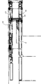
Fig. 2 is the paper sheet handling apparatus (pre-acceptor: the figure of transfer system structure preparatory receiver) of this embodiment of explanation.
Fig. 3 A is the structure of explanation clamp device (clamp) and the vertical view of drive system thereof.
Fig. 3 B is the structure of explanation clamp device and the side view of drive system thereof.
Fig. 3 C is the structure of explanation clamp device and the front elevation of drive system thereof.
Fig. 4 is explanation has applied pressure status to the stacked bank note that is inserted with clamp device figure.
Fig. 5 is the figure that explanation is arranged at the configuration that drops near the sensor of escape hole.
Fig. 6 is the circuit structure diagram of the bill handling device of this embodiment.
Fig. 7 A is the figure (upper end position) that the method for the stacked bank note height that inserts with sensor is described.
Fig. 7 B is that the figure that the method for the stacked bank note height that inserts with sensor is described (can take in the position: one of which).
Fig. 7 C is the figure (can take in the position: they are two years old) that the method for the stacked bank note height that inserts with sensor is described.
Fig. 7 D is the figure (lower end position) that the method for the stacked bank note height that inserts with sensor is described.
The figure of the stacked bank note of income condition is satisfied in Fig. 8 A explanation.
The figure of the stacked bank note of income condition is not satisfied in Fig. 8 B explanation.
Fig. 9 explains the figure of the deflection measuring method of stacked bank note.
The figure (one of which) of the working condition of the preparatory receiver when Figure 10 A is the explanation deposit.
The figure (its two) of the working condition of the preparatory receiver when Figure 10 B is the explanation deposit.
The figure (its three) of the working condition of the preparatory receiver when Figure 10 C is the explanation deposit.
The figure (its four) of the working condition of the preparatory receiver when Figure 10 D is the explanation deposit.
The figure (its five) of the working condition of the preparatory receiver when Figure 10 E is the explanation deposit.
The figure (its six) of the working condition of the preparatory receiver when Figure 10 F is the explanation deposit.
The figure (its seven) of the working condition of the preparatory receiver when Figure 10 G is the explanation deposit.
The figure (one of which) of the working condition of the preparatory receiver when Figure 11 A is the explanation payment.
The figure (its two) of the working condition of the preparatory receiver when Figure 11 B is the explanation payment.
The figure (its three) of the working condition of the preparatory receiver when Figure 11 C is the explanation payment.
The figure (its four) of the working condition of the preparatory receiver when Figure 11 D is the explanation payment.
The figure (its five) of the working condition of the preparatory receiver when Figure 11 E is the explanation payment.
The figure (its six) of the working condition of the preparatory receiver when Figure 11 F is the explanation payment.
Figure 12 is the process flow diagram that gathering is handled.
Figure 13 is the process flow diagram that income is handled.
Figure 14 returns the process flow diagram of handling.
Figure 15 is that bank note is discharged the process flow diagram of handling.
Figure 16 is the process flow diagram of accommodating processing.
Figure 17 is the process flow diagram that payment is handled.
Figure 18 is the figure of the variation of explanation suspension hook (hook).
Figure 19 is the figure of the variation of explanation carriage (tray).
The best mode that carries out an invention
Below, with reference to accompanying drawing embodiment of the present invention is elaborated.
Fig. 1 is the cut-open view of the bill handling device of this embodiment.
This bill handling device 1 be a kind of be prerequisite to be used in automation equipment, for example automatic teller machine (ATM), be used for handling device as the bank note of paper class.As shown in Figure 1, its structure possesses: preparatory receiver (Pre-accsptor) 100, and it inserts by when surpassing one the overlapping stacked bank note B that forms of bank note client, should take in inside by stacked bank note B; Lower unit 200, it accommodates bank note; And upper unit 300, it is at lower unit 200 and transmit bank note between the receiver 100 in advance.Receiver 100 is equivalent to the paper sheet handling apparatus of this embodiment in advance.Should be stated as " receiver " perhaps " PAC " by preparatory receiver 100 in the back.
Working condition to said structure describes.Bill handling device 1 is a kind of device of depositing and withdrawing.Therefore, will be to the explanation of its working condition, describe during with payment when being divided into gathering.The automation equipment of having loaded said apparatus is prerequisite with ATM, that is to say that bill handling device 1 is to be prerequisite according to the situation of carrying out work from the indication of ATM main body.
The input escape hole 101 that is arranged at receiver 100 is the oral areas that are used to operate as follows,, drops into the stacked bank note B that client deposits usefulness that is, perhaps discharges the stacked bank note B that uses to customer payment to the outside.It is loaded on the ATM, but and disposes the baffle plate (not shown) of switch in the outside of dropping into escape hole 101.Below, from client's angle, and input escape hole 101 sides of receiver 100 are called front face side, and its opposition side is called the back side.In addition, see from lower unit 200, with upper unit 300 sides as the top, and with its opposition side as the below.
Working condition during at first, to gathering is elaborated.This gathering is such as carrying out through following mode, that is, client operates ATM operating portion (not shown), and proposes deposit request.If client has proposed deposit request, then the ATM main body makes baffle plate open and transfer to and can stacked bank note B be inserted (input) to the state that drops into escape hole 101, indicates the bundle of papers class B to being inserted into bill handling device 1 to take in then.
Be used for sensor that the stacked bank note B that is inserted is detected dropping into to dispose near the escape hole 101.If bill handling device 1 receives this indication from the ATM main body, wait until that then this sensor transmits after stacked bank note B.Transmit through this, be carried to separation vessel (SEP) portion 310 of upper unit 300 through transfer path 102 and with stacked bank note B.For delinquency prevention, bill handling device 1 is embedded in the wall, and makes the client operating portion that drops into escape hole 101 and ATM expose to wall, can let the structure of client operating and form.Therefore, no matter be when dropping into the stacked bank note B of escape hole 101 incomes, or when dropping into escape hole and discharging stacked bank note B, stacked bank note B transmits via transfer path 101.So, even bill handling device 1 is being embedded under the situation in the wall, because stacked bank note is transmitted, drops into and discharge with becoming, so the processing of bank note becomes simple concerning client.
If bill handling device 1 has been taken in the stacked bank note B that client inserted, then give the ATM main body with its result notification.The ATM main body is closed baffle plate according to this notice.
Be provided with delivering mechanism 311 in the bottom of separator section 310, this delivering mechanism 311 is used for more than seeing bank note off from stacked bank note B.This delivering mechanism 311 adopts for example known structure.Particularly, it adopts the structure that for example possesses like lower member: pick-up roller (pick roller), and it is given and is positioned at the power that nethermost bank note transmits transport direction; Feed rollers (feed roller), it transmits the bank note of being seen off by this pick-up roller; And separation vessel, its its being configured to this feed rollers state of contact, and be used for preventing that bank note is by dual conveyance.
Through being sent to separator section 310 from receiver 100, and stacked bank note B is carried in the platform portion 312 of state as shown in Figure 2.This one 312 and be positioned at its top pusher (pusher) 313 can move up at upper and lower together.So, stacked bank note B being sent to the transmission of the position that delivering mechanism 311 can see bank note off, is to carry out through the mode that platform portion 312 is moved downwards.Because the position shown in Figure 2 of platform portion 312, pusher 313 is in the upper end in the mobile range respectively, so it all is called upper end or upper end position.
As everyone knows, seeing off of bank note need make bank note and pick-up roller contact with suitable pressure.Pusher 313 is used for pressurizeing, and utilizes its pressure that they are contacted.This pressurization can be carried out according to following mode, that is, platform portion 312 is moved to after the lower end downwards, pusher 313 is moved downwards, and exert pressure from the top of stacked bank note B.
The platform portion 312 that moves to the pick-up roller lower end is supported by not shown elastic component, and becomes the state that can move at above-below direction.Whether this is to be applied with for the suitable pressure of seeing off of bank note in order from the change in location of pick-up roller platform portion 312, to judge.Therefore, be provided with sensor, this sensor is used to detect the pick-up roller platform portion 312 that is applied in upward pressure and moves to lower end position downwards.Keep watch on the testing result of this sensor, and pusher 313 moves downwards, so that apply suitable pressure.Thus, prepare drive system that platform portion 312, pusher 313 are moved in addition individually.All adopt stepper motor (stepping motor) as its power source that moves usefulness.
Through delivering mechanism 311 many bank note of seeing off from separator section 310, be sent to discriminating portion 320 through transfer path 301 and by being differentiated.Differentiate through this, carry out this bank note whether differentiation of normal certificate and confirming the denomination kind of normal certificate.False bank note, the bank note that can't differentiate, or damaged bank note, being differentiated is unusual certificate.Bank note after the discriminating is transmitted through transfer path 302.
In upper unit 300, be provided with 3 discarded grooves (reject box) 351~3.In case be provided with the interim preservation portion 330 that is used for temporarily accommodating the input bank note of client.Also be formed with respectively in addition and be used for and can bank note accommodated the transfer path 303 of interim preservation portion 330 and is used for can bank note being accommodated any one transfer path 304 of discarded groove 351~3.
2 that in transfer path 302, dispose the transmission destination that is used to switch bank note switch pawl 302a, 302b.Bank note in transfer path 302 transmits follow the transfer path of process, can switch through following mode respectively:, it is switched to transfer path 303 through switching pawl 302a; Through switching pawl 302b, it is switched to transfer path 304.Through switching pawl 302a, the bank note after the discriminating is sent to transfer path 303 from transfer path 302, and is contained in the interim resettlement section 330.
In interim resettlement section 330, be provided with on above-below direction movably 2 platform portions 331,332.Platform portion 331 and platform portion 332 are used in is respectively differentiated accommodating and differentiated accommodating for the bank note of normal certificate for the bank note of unusual certificate.Here, for the ease of explanation, will be called reservoir (reservoir) by the resettlement section that platform portion 331 realizes, and will be called trustship (escrow) portion by the resettlement section that platform portion 332 realizes.In addition, platform portion 331 is called RSV platform portion, and platform portion 332 is called ESC platform portion.
These ones 331,332 are installed on the travelling belt 335, and 335 tensions of this travelling belt are arranged at 2 belt wheel rollers (pulley-roller) 333 of being provided with separating certain intervals on the above-below direction, between 334.Prepare 2 belt wheel rollers 333,334 and travelling belt 335 respectively through relative each one, move and each one 331,332 can be distinguished individually.
Dispose one at transfer path 303 and switch pawl, so that between reservoir and trustship portion, select the transmission destination of bank note.Thus, will pass through transfer path 303 and the bank note that transmits is accommodated in reservoir or the trustship portion.Dispose 2 at transfer path 304 and switch pawls, be used for bank note is accommodated among any one of discarded groove 351~3.
For all bank note that many are seen off from separator section 310, all carry out by the discriminating of the bank note of discriminating portion 320 and according to its identification result and accommodating to interim preservation portion 330.Therefore, the bank note from separator section 310 is seen off after the end, according to the identification result by discriminating portion 320, the depositing bank paper of seeing off is contained in the reservoir or trustship portion of interim preservation portion 330.The end of seeing off judges through following mode, that is, confirm with sensor and in separator section 310, do not had bank note, perhaps confirms to see off still do not have bank note to be sent in the transfer path 301 carrying out with sensor.
If with the accommodate end of the input bank note of the form of stacked bank note B to interim resettlement section 330, then bill handling device 1 is notified this result to the ATM main body.Discriminating portion 320 will be counted according to the denomination kind for the number of the bank note of normal certificate by differentiation, and the amount of money that is calculated is also notified in the lump.According to these notices, the ATM main body is pointed out deposit to client, and the establishment of whether concluding the business, has or not consultings such as appending deposit.Afterwards, the result according to consulting carries out work.
When customer requirement appended deposit, the ATM main body was opened baffle plate once more, and indication is taken in the bundle of papers class B that is inserted in the bill handling device 1.As stated, the bank note of the formation stacked bank note B that client inserted is housed in the reservoir or trustship portion of interim resettlement section 330.
When customer requirement Cancelled Transaction, the bank note of taking in to the bill handling device 1 was returned in ATM main body indication.Usually, this bank note be housed among the reservoir, trustship portion of interim resettlement section 330, or be contained in simultaneously these both in.The position that bill handling device 1 is accommodated according to bank note, and return according to following mode.
Above interim preservation portion 330, be provided with the transfer path 305 that is used to transmit stacked bank note B.This transfer path 305 can be sent to receiver 100 with the stacked bank note B that is housed in the interim preservation portion 330.The transmission of stacked bank note B in this transfer path 305 is to utilize carrier (carrier) 341 and be held under the situation of overlapping state to carry out.Such as, such shown in Figure 11 A, this carrier 341 is to be used for device that the form that stacked bank note B pushes away with the rear from its direction of transfer is transmitted.Through so transmitting, and the overlapping stacked bank note B that forms of each bank note adopts by the supported form of carrier 341.Therefore, can be suitably and transmit stacked bank note B reliably, thereby can avoid reliably bank note in transmission to the outstanding situation of direction of intersecting with overlapping direction.
Also be provided with a plurality of gears that are used for to carrier 341 transferring power at transfer path 305.The transmission of power that carrier 341 passes through from this gear, and can move along being arranged on the ways (not shown) on the transfer path 305.Thus, according to this position of carrier 341 on transfer path 305, also different to the gear of carrier 341 transferring power.In each one 331,332,312, also be provided with this ways.
Only in reservoir, contain under the situation (case) of bank note, make RSV platform portion 331 move to the position (discharging (release) position) on the transfer path 305.At this moment, carrier 341 position (trustship retreating position) that moved into place the platform portion 331 back sides on this off-position is located.After the position (off-position) that this carrier 341 is moved to receiver 100 fronts is located, the stacked bank note B in the platform portion 331 is sent to input escape hole 101 with receiver 100.For baffle plate is opened, such as make carrier 341 move to the off-position the time ATM main body notified.The position of the carrier 341 before the transfer table portion 331 and the moment of notifying to the ATM main body, also basic identical for other situation.
Only in trustship portion, contain under the situation of bank note, RSV platform portion 331 is moved to its position (upper end position) of keeping out of the way on the transfer path 305 is located, and the position (off-position) that ESC platform portion 332 is moved on the transfer path 305 is located.After the position (off-position) that carrier 341 is moved to receiver 100 fronts is located, the stacked bank note B in this one 332 is sent to input escape hole 101 with receiver 100.
Contain under the situation of bank note in reservoir and the both of trustship portion, the position (off-position) that RSV platform portion 331 moves on the transfer path 305 is located.At this moment, platform portion 312 and pusher 313 being in respectively makes them move to the state at upper end position place.Through making carrier 341 move to separator section 310, and the stacked bank note B in the RSV platform portion 331 is carried in the platform portion 312.Then, platform portion 312 is moved downwards, and pusher 313 is moved to be positioned at the ready position that converges at platform portion 312 upper end position places.After pusher 313 being moved to converge ready position, make fork as shown in Figure 1 (fork) portion 342 outstanding to pusher 313 (front).After it is outstanding, make pusher 313 move to upper end position.
Because bank note has elastic force, the bank note that has therefore been bent has the tendency of keeping its bending state.Therefore, when bank note is merely overlapping, it highly changed according to acting on the elastic force on each bank note.The bank note that has been bent is many more, and then it has the tendency that uprises highly more.Therefore, for fear of making stacked bank note B in the platform portion 312 outstanding and be provided with fork portion 342 on transfer path 305.
With along transfer path 305 and converge on the height of ready position can give prominence to, and the mode that can keep out of the way from outstanding state be provided with this fork portion 342.Pusher 313 is provided with recess, gives prominence to so that carry out this.Thus, under the state of pushing down the stacked bank note B in the platform portion 312 with pusher 313, make fork portion 342 outstanding, and make pusher 313 move to above after push down stacked bank note B with fork portion 342, to allow it is given prominence on transfer path 305.
The stacked bank note B that is sent to separator section 310 is moved in the fork portion 342.After this stacked bank note B is handled upside down, fork portion 342 is kept out of the way.Thus, in platform portion 312, the stacked bank note B that is contained in the reservoir becomes one folded with stacked bank note B in being contained in trustship portion according to its order is overlapping and range upon range of.Through platform portion 312 is moved to upper end position, and with carrier 341 with the place, off-position that stacked bank note B stacked together is sent to receiver 100, further be sent to input escape hole 101 places with receiver 100.Thus, return to client.
Like this, in this embodiment, stacked together and return with being housed in bank note in reservoir and the trustship portion respectively.This is for fear of owing to returning the situation that client that the bank note be housed in them takes place has forgotten to fetch bank note respectively.Client has forgotten the bank note fetched, such as being housed in the discarded groove 353.
In customer requirement transaction (deposit), the ATM main body is to the bank note of bill handling device indication collecting post income.This bank note be housed in interim resettlement section 330 reservoir, trustship portion, or be housed in them simultaneously among both.Accommodate according to following mode the position that bill handling device 1 is accommodated according to bank note.
Unusual certificate, just differentiated for the bank note of normal certificate and can be housed in the reservoir.Therefore, only in reservoir, contain under the situation of bank note, this bank note can be returned.The working condition of this moment, the situation of the bank note of only in reservoir, accommodating being returned with requiring according to client's cancellation is basic identical.
Only in trustship portion, contain under the situation of bank note; RSV platform portion 331 is moved to make it to keep out of the way the upper end position to the transfer path 305; And the off-position that ESC platform portion 332 is moved on the transfer path 305, and the stacked bank note B in this one 332 is sent to separator section 310.From the stacked bank note B that is transmitted, more than of bank note are seen off in separator section 310, and be sent to lower unit 200 through transfer path 301, discriminating portion 320 and transfer path 302.
In lower unit 200, be mounted with according to the denomination kind of the bank note of being accommodated and cassette 210 removably.Top in each cassette 210 that is loaded is provided with delivering mechanism 211, and this delivering mechanism 211 can carry out accommodating of bank note and seeing off the bank note of being accommodated.Be sent to the bank note in the lower unit 200, in transfer path 201, transmit, and guide in the cassette 210 that to be accommodated, accommodate through delivering mechanism 211 then through the switching pawl that is arranged on this transfer path 201.Thus, the bank note of client's insertion is contained in the cassette 210 according to the denomination kind.
In reservoir and trustship portion, all contain under the situation of bank note, be housed in the reservoir bank note as described above mode return to client, and the bank note that only will be housed in the trustship portion is sent to separator section 310.The bank note that is transmitted more than is seen off in separator section 310; And the bank note of being differentiated for normal certificate is sent to lower unit 200 through transfer path 301, discriminating portion 320 and transfer path 302, is housed in the cassette 210 according to the denomination kind then.Differentiated for the bank note of unusual certificate through transfer path 301, discriminating portion 320, transfer path 302 and transfer path 304 be housed in discarded groove 351, or 352 in.Perhaps, after temporarily being housed in the reservoir, be resent to separator section 310, and carry out the whether unusually discriminating of certificate once more.After being housed in the reservoir, return to client through 3.
So; In this embodiment; The bundle of papers class B that client inserts keeps its state and is transferred into separator section 310; Carry out then seeing bank note off, and will see off after the bank note of differentiating is housed in interim preservation portion 330, transmit and return, or move to this separator section 310 with the state of stacked bank note B from stacked bank note B.Thus, compare, can further shorten many transmitting ranges that transmit bank note with more than situation of seeing off and transmitting of bank note that will after differentiating, accommodate.Thus, can further be reduced in the probability that faults such as card coin take place in the transmission, so can further improve reliability.In other words, do not wait, need on short side direction, transmit, but the ways that transmits to the long axis direction record can't be set in order to carry out high speed processing such as the wide 60mm of being of the coin of Euro~86mm.Therefore, when a Zhang Jinhang transmits, seize on both sides by the arms and transmit, so be easy to take place deflection etc. with travelling belt.If transmit, then be difficult for deflection etc. takes place, but processing power can reduce with low speed.Therefore, for the problem that transmits under the situation that does not reduce processing power, can solve through being held in the mode that overlapping state transmits.
Be arranged on the structure that delivering mechanism 311 on the separator section 310 has adopted the complicacy that possesses various rollers and separation vessel.In order suitably to carry out seeing off of bank note, must possess being used for applying mechanism and a plurality of sensor of suitable pressure to bank note.Thus, one-piece construction becomes very complicated., be sent to separator section 310 with the state of stacked bank note B, can avoid preparing in addition the device as the delivering mechanism 311 that is used to see off the bank note of being accommodated through differentiating the back bank note of being accommodated.Owing to see bank note off from same position, therefore,, the part that can realize communization in the transfer path is increased even the transmission destination of many bank note of seeing off is different.Its result can make the whole mechanism simplifying of device, can also suppress production cost thus.
Working condition during then, to payment is elaborated.This course of payment carries out through following mode,, such as the operating portion of client operating ATM, seek out the fund of designated amounts that is.If client has carried out above-mentioned requirements, then 1 discharge of ATM main body indication bill handling device is corresponding to the bank note of the amount of money of withdrawing the money.When client has specified needed bank note, its given content is notified to paper kind processing device 1.
If bill handling device 1 receives this indication from the ATM main body,, and, from the cassette 210 that should see bank note off, more than of bank note are seen off with delivering mechanism 211 according to this decision then such as the number that determines to see off bank note according to the denomination kind.The bank note of being seen off passes through the transfer path 306 of transfer path 201 and upper unit 300 and is transferred into discriminating portion 320, and differentiates.Differentiate through this and also to differentiate the denomination kind when whether being the normal certificate that to pay, will be differentiated then, discarded groove 351, perhaps 352 and will differentiate for the bank note of unusual certificate is sent to for the bank note of normal certificate be sent to trustship portion.
Transmission to the bank note of trustship portion is performed until till the bank note of having accommodated corresponding to the specified amount of money of withdrawing the money of client.Corresponding to the bank note of this amount of money of withdrawing the money accommodate end after, same with the situation of returning the bank note of only in trustship portion, accommodating, carrier 341 is moved to after the off-position of receiver 100 fronts, be sent to input escape hole 101 with receiver 100 again.
Like this, the bank note during payment also is transferred into input escape hole 101 places of receiver 100 with the state of stacked bank note B.Thus, even near input escape hole 101, can guarantee space is very little, also bill handling device 1 can be set.
Above-mentioned receiver 100, lower unit 200 and upper unit 300 have been realized modularization respectively.This is because following reason is arranged.
As everyone knows, use the bill handling device on automation equipments such as ATM to be set in the national treasury.Usually, even same financial institution, this national treasury is according to automation equipment and separately different.Therefore, under normal conditions, bill handling device environment is set, such as being arranged on cassette exchange in the national treasury, according to automation equipment and different separately with the position of door, the wall thickness of national treasury etc.Thus, be the bill handling device that designs and made and be provided with the environmental facies adaptation as required in the past.
, if receiver 100, lower unit 200 and upper unit 300 are realized modularization respectively, can make the wall thickness of national treasury corresponding so according to the selection of the receiver that is adopted 100 with it.Move lower unit 200 through changing, perhaps be housed in the direction of cassette 210 wherein, and can make the diverse location of the door that is arranged on national treasury corresponding with it.Thus, need not carry out basically based on the design that environment is set, thus the necessity that can avoid carrying out this design.Its result can further control the manufacturing cost of bill handling device 1, and for the manufacturer, also can more promptly prepare the bill handling device 1 of delivering goods.
Then, with reference to figure 2~Fig. 5 the structure of receiver 100 is carried out detailed explanation.
Fig. 2 is the figure of the transfer system structure of explanation receiver 100.As shown in Figure 2, the structure of receiver 100 possesses: clamp device 103, and it is arranged on transfer path 102 tops; Carriage 104, it is arranged on transfer path 102 belows; Suspension hook 105, it is installed on this carriage 104; Travelling belt 106, it is used for transmitting stacked bank note B along transfer path 102; Scrambler (encoder) 107, it is used to confirm the conveying capacity by the stacked bank note B of travelling belt 106 transmission; Sensor 109~112, they are arranged on the diverse location on the transfer path 102; Limiter (stopper) 113,114, they are arranged on the diverse location on the transfer path 102, and can carry out outstanding on transfer path 102 and keep out of the way.With the direction of transfer of stacked bank note B crisscross on, dispose a plurality of suspension hook 105, limiter 113,114 with side by side form.
Above-mentioned scrambler 107 possesses: disc 107a, and it is along with to the rotation of the motor of travelling belt 106 transferring power and rotate; Detect the sensor 107b that slit is used, it is arranged on the circumference of this disc 107a.This sensor 107b is a kind of optical sensor with light-emitting component and photo detector.From the light of this light-emitting component outgoing, the quilt shading by spells owing to the rotation of disc 107a.Therefore, from the photo detector output pulse signal, thereby through this pulse signal being counted confirm actual conveying capacity.
Above-mentioned carriage 104 is a kind ofly to be supported from dropping into the member of the stacked bank note B that escape hole inserted by tabular component.Suspension hook 105 mounted thereto can be given prominence on transfer path 102 and keep out of the way.When stacked bank note B was inserted into, as shown in Figure 2, it was used to guide the length that should insert of stacked bank note B.
This input escape hole 101 forms can be with the range upon range of input together of the bank note about 200.Therefore, transfer path has the height about 25mm.
On Fig. 2, see, utilize to bring and realize carriage 104 moving along transfer path 102 with the transmission of straining setting with travelling belt 106 overlapping modes.In order to confirm its amount of movement, also prepared the scrambler 107 of that kind as shown in Figure 2 in addition.For limiter 113,114, for fear of confusion, the limiter that is arranged on front face side 113 is called the A limiter, and will be arranged on the back side limiter 114 be called the D limiter.
Fig. 3 A~Fig. 3 C is the structure of the above-mentioned clamp device 103 of explanation and the figure of drive system thereof.
Shown in Fig. 3 A, this clamp device 103 is that a kind of utilization comprises a plurality of axostylus axostyles of axostylus axostyle (shaft) 121,122 and stacked bank note B transmitted 4 devices that travelling belt 123 supports with tension of usefulness.Be positioned on the top axostylus axostyle 121, the ways 124 of the insertion usefulness of a plurality of stacked bank note B is being installed.Transmit the power that is used to make travelling belt 123 rotations through an axostylus axostyle, such as axostylus axostyle 121.This power also is passed on the travelling belt 106 that is disposed at downside.
The stacked bank note B that inserts in order to make is in the state of seizing on both sides by the arms between itself and carriage 104, so that clamp device 103 can along with transfer path 102 directions crisscross on move.Make this move the drive system that is achieved, the arm 131,132 of the both end sides through being installed in axostylus axostyle 121,122 respectively realizes that this moves.Transmission of power to arm 132, this power further is passed to arm 131 through connecting rod 133 then.
Shown in Fig. 3 B, arm 131,132 is that the center can be rotated with axle 131a, 132a respectively.End at them also is formed with recess 131b, 132b respectively, and axostylus axostyle 121,122 can be installed in this recess 131b, 132b with rotating freely.On circular-arc end 132c of being of the opposing party of arm 132, be formed with profile of tooth, this profile of tooth is meshed with the profile of tooth of gear 135.
Shown in Fig. 3 C, this gear 135 is installed in the end of axostylus axostyle 134.The opposing party end at axostylus axostyle 134 is equipped with belt wheel roller 136.At above-mentioned belt wheel roller 136 be installed in that tension is provided with rotating band 137 between the belt wheel roller 139 of axostylus axostyle 138 ends.
Through make clamp device 103 from state transitions shown in Figure 2 to state as shown in Figure 4, applied downward pressure to stacked bank note B, and it seized on both sides by the arms between clamp device 103 and carriage 104.This stacked bank note B need not to apply the pressure that exceeds necessity.According to by the situation of overlapping bank note, and the height of this stacked bank note B also may change, so can't know the height when having applied enough pressure in advance.Therefore, in this embodiment, if adopted the resistance that the overshoot value takes place just to make the one-way engagement device (oneway clutch) of its idle running be used as contact maker 144.Thus, realized and to have applied suitable pressure reliably to stacked bank note B.
Owing to receive from applying the crisscross of tension direction and go up applied force, so significantly distortion takes place travelling belt.This distortion more strengthens the variation of stacked bank note direction of transfer, and stacked bank note is received do not hope the power that receives.Because above-mentioned situation if only use travelling belt, then is difficult to stacked bank note is suitably applied enough pressure.If dispose the belt wheel roller that supports travelling belt with shorter interval, can suitably apply bigger pressure though then become, number of components increases and makes structure become complicated, thus manufacturing cost also is enhanced.
But, can use member for above-mentioned carriage 104 with enough rigidity.Therefore, also can when keeping its state, support even exert pressure stacked bank note B.Therefore, compared when exerting pressure, can suitably apply bigger pressure with seizing on both sides by the arms between travelling belt.Act on the unwelcome power of stacked bank note in can reducing to transmit.Its result becomes when can keep stacked bank note state, can more suitably transmit.
As shown in Figure 4, connecting rod 133 is provided with 3 slit 133a~c, and disposes 2 sensors 145,146 that can detect these slits 133a~c.These sensors 145,146 all are optical sensors, and it is according to only not detected slit 133a~c by shading from the light-emitting component outgoing.
Fig. 5 is the figure that explanation is arranged on the configuration that drops near the sensor the escape hole 101.Near the sensor 109~111 that it, is provided with and be arranged on the back side sensor 112 all be optical sensor.
As shown in Figure 5, with stacked bank note B sidewards, also align between the ways 151 with regard to saying its long axis direction to be intersected with direction of insertion and be inserted into width.As sensor 109 4 sensor 109a~d are configured side by side, so that can judge whether the width (length of long axis direction) that is inserted into the stacked bank note B in the input escape hole 101 is normal certificate.Utilize this sensor 109a~d and sensor 110 to judge whether this stacked bank note B is the bank note that take in.Shown in Fig. 8 A, the condition that the stacked bank note B that should take in satisfy does, can detect stacked bank note B with sensor 110 and sensor 109b, c, and then, also can detect stacked bank note B with among sensor 109a, the d any one.For the stacked bank note B that does not satisfy above-mentioned condition such shown in Fig. 8 B, the refusal income.
Sometimes stacked bank note B can be inserted into the state of deflection and drop into escape hole 101.To the detection of this deflection situation, can utilize sensor 109b, c, and be that object carries out only with the stacked bank note B that satisfies the income condition.
If deflection has taken place in stacked bank note B, then with it when transmit inside, on sensor 109b, c detect less than time point, produce deviation.If this mistiming is made as Δ T, transfer rate is made as V, sensor 109b then shown in Figure 9, the departure X between the c do
X=V·ΔT
Therefore, if the distance between sensor 109b, the c is made as Y, the deflection θ that representes with angle so (°) can try to achieve with following formula.
θ=tan
-1(X/Y)
Only when but its deflection is in the allowed band, just proceed income to stacked bank note B.
As stated, the length of the long axis direction of stacked bank note B is confirmed to utilize sensor 109a~d to carry out.The length of its short-axis direction is confirmed it is to carry out through following mode, that is, but confirm whether sensor 111 to be begun to removing the length that transmitted till the above-mentioned shading state, being within the allowed band by the position of shading from stacked bank note B is sent to.The height detection of stacked bank note B be through counting clamp device 103 pressurizeed after, its rotation amount that turns back to the required motor of upper end position 140 is carried out.
Shown in Fig. 7 A, sensor 145,146 is in transmissive state simultaneously at the upper end position place.Therefore, through the signal that monitoring sensor 145,146 is exported, the height till just can confirming from position that stacked bank note B is pressurizeed to upper end position.Thus, the height of stacked bank note B, the mode that can deduct its height through clamp device 103 and the height between the carriage 104 from upper end position is calculated.
Like this, in this embodiment, carry out the size of stacked bank note B is confirmed (length of major axis, minor axis both direction is confirmed) with receiver 100, deflection θ, with and the measurement of height.So, can unsuitable stacked bank note B be returned to client, thereby can realize the utilization ratio of more increasing in the stage more early.Working condition for realizing said process describes later on again.
Fig. 6 is the circuit structure diagram of bill handling device 1.
The structure of above-mentioned receiver 100 possesses sensor groups 161, groups of motors 162 and solenoid (solenoid) group 163.Sensor groups 161 is made up of sensor 107b of the sensor 109~112,145,146 and scrambler 107 etc.Groups of motors 162 is by constituting as follows: as the motor 140 of the power source that clamp device 103 is moved; The drive motor that tension is arranged at the travelling belt 123 on the clamp device 103 and thereunder strains the travelling belt 106 that is provided with; Carriage 104 moves uses motor.These motors all are stepper motors.Suspension hook 105, A limiter 113 and D limiter 114 outstanding and keep out of the way and all utilize solenoid to carry out.Solenoid group 163 is made up of these solenoids.
Groups of motors 271 is such as being made up of a plurality of stepper motors.Each stepper motor is used as being used for moving the power source that is arranged on the platform portion in the corresponding cassette 210.Groups of motors 272 is such as being made up of a plurality of DC motors.Each DC motor is used as the power source that is arranged on the delivering mechanism 211 in the corresponding cassette 210.
On printed circuit board (PCB) 260, be mounted with: carry out CPU261 the control of bill handling device 1 integral body; Store the ROM262 of performed program of this CPU261 and various control datas; CPU261 is used in the RAM263 of computing; Drive the sensor drive portion 264 of the sensor that constitutes sensor groups 273; Individual drive constitutes the solenoidal solenoid-activated portion 265 of solenoid group 274 in addition; Drive the motor driving part 266 of the stepper motor that constitutes groups of motors 271; Drive the motor driving part 267 of the DC motor that constitutes groups of motors 272; Be used for such as the communication interface (I/F) 268 that communicates with upper unit 300; Be used for such as the communication interface (I/F) 269 that communicates with epigyny devices such as ATM main bodys.
Groups of motors 371 is such as being made up of a plurality of stepper motors.Carrier 341, each one 312,331,332 and pusher 313 move stepper motor respectively as power source.DC motor 372 is to be used for the power source bank note being seen off and transmitted from separator section 310.
On printed circuit board (PCB) 360, also be mounted with: carry out CPU361 the control of upper unit 300 integral body; Store the ROM362 of performed program of this CPU361 and various control datas; CPU361 is used for the RAM363 of computing; Drive the sensor drive portion 364 of the sensor that constitutes sensor groups 373,161; Drive the motor driving part 365 of the stepper motor that constitutes groups of motors 371,162; Drive the motor drive circuit 366 of DC motor 372; Individual drive constitutes the solenoidal solenoid-activated portion 367 of solenoid group 374,163 in addition; And discriminating portion 320 between carry out the interface (I/F) 368 that the transmission of signal receives; And be used for the communication interface (I/F) 369 that communicates with lower unit 200.
Working condition to said structure describes.
CPU261,361 on each printed circuit board (PCB) 260,360 controls through carrying out the program that is stored in respectively among the ROM262,362.CPU261 receives the indication from the ATM main body through communication I/F269, and carries out the control to lower unit 200 according to this indication, assigns the indication to upper unit 300 then.Pass through communication I/F268,369, and the CPU361 of upper unit 300 is delivered in this indication.
At any time receive that CPU261 makes these sensor drive portion 264 driving sensor groups 273 and the various testing results that obtain by sensor drive portion 264; And, by communication/F268, or 269 receive the content that communicates by upper unit 300 or ATM main body at any time.Analyze these testing results and Content of Communication, and assign according to the indication of situation separately to solenoid-activated portion 265, motor driving part 266,267.So, under the control of CPU261, make lower unit 200 work.In addition, via communication I/F268, or 269, and the information that should notify at any time sends.
According to indication from lower unit 200, the CPU261 of the opposing party's upper unit 300 control upper unit 300 and receiver 100.This control is to carry out according to following mode; Promptly; At any time receive and analyze the various testing results that make sensor drive portion 364 driving sensor groups 373,161 and obtain by sensor drive portion 364, and the indication that makes solenoid-activated portion 367, motor driving part 365, motor drive circuit 366 and discriminating portion 320 assign basis situation is separately carried out.Thus, under the control of CPU361, make upper unit 300 and receiver 100 work.Assign indication through I/F368, and sending at any time via communication I/F369 should be to the information of lower unit 200 notices to discriminating portion 320.When the stacked bank note B that client is inserted takes in, with deposit as its information, when bank note is accommodated, will be differentiated for the denomination kind of normal certificate etc. as information, and send to lower unit 200.
Below, with reference to Figure 12~process flow diagram and Figure 10 A~Figure 10 G shown in Figure 17, the key diagram shown in Figure 11 A~Figure 11 F carries out detailed explanation to the working condition of bill handling device 1.Its working condition realizes that through following mode promptly, the CPU261 of lower unit 200 controls this lower unit 200, and the CPU361 of upper unit 300 controls this upper unit 300 and receiver 100 respectively under the control of this CPU261.The figure of the working condition of the receiver 100 when Figure 10 A~Figure 10 G is the explanation deposit, and Figure 11 A~Figure 11 F is the figure of the working condition of explanation this its when payment (comprising return).
Figure 12 is the process flow diagram that gathering is handled.This processing is to carry out for the indication of being assigned according to the ATM main body realizes the desired deposit operation of client.At first, with reference to Figure 12 the gathering processing is elaborated.
The various piece of lower unit 200 is under the control of CPU261, to work, and the various piece of upper unit 300 and receiver 100 is under the control of CPU371, to work.Therefore, the CPU that is conceived to the Control work object here describes.
At first, in step 101, confirm in the position shown in Fig. 2 and Figure 10 A, promptly transmit on (delivery) position whether have carriage 104, and if not on this delivering position, then it is moved to this position.In next procedure 102, judge at input escape hole 101 places whether detected the bank note that satisfies income condition (Fig. 8 A).Be inserted into when the stacked bank note B that drops into escape hole satisfies the income condition client, be judged as " being " and transfer to step 104.When being not above-mentioned situation, being judged as " denying " and transferring to step 103.Satisfying should the income condition, and the long axis direction length that means stacked bank note B is within allowed band.
The processing of above-mentioned steps 101,102 is indicated the control of CPU361 of upper unit 300 of the income of stacked bank note B to realize through the CPU261 from lower unit 200.After step 103~118 stated also be the same.Be arranged near drop into the escape hole 101 baffle plate, be opened after being performed such as processing in step 101.Suspension hook 105 is outstanding state usually.
In step 103, judge from beginning whether the detection of stacked bank note B has been passed through the regular hour.If passed through this certain hour, then be judged as " being ", and finish a series of processing at this.When being not above-mentioned situation, being judged as " denying ", and turning back to above-mentioned steps 102.Thus, wait for that stacked bank note B is inserted into, till the process certain hour.
Though do not illustrate especially, become " being " stage before in the judgement of this step 103, be not inserted into the situation of stacked bank note B from CPU361 to the CPU261 notice, and further notify above-mentioned situation to the ATM main body from CPU261.Through notifying, and be implemented in be judged as " being " that the ATM main body makes step 103 after the flapper closure with such timing.
On the other hand, in step 104, the position when carrier 341 is moved into stacked bank note B is carried to separator section 310, shown in Figure 10 F, accept the position, and pusher 313, platform portion 312 move to the upper end position shown in Figure 10 A respectively.In back to back step 105, such shown in Figure 10 B, CD-ROM drive motor 140 and carry out pressurization by clamp device 103, and detect the height (with reference to figure 4, Fig. 7 A~Fig. 7 D) of stacked bank note B by sensor 145,146.Number (number of steps) through CPU361 specifies sense of rotation and applies from pulse to motor driving part 365 indicates it to drive, and carries out the driving as the motor 140 of stepper motor.About this point, also identical for other stepper motor.
In the step 105a that then transfers to, judge that highly whether it within allowed band.If stacked bank note B is the height that can take in, then shown in Fig. 7 A~Fig. 7 D, clamp device 103 is moved downwards during, sensor 145 from the state exchange of transmitted light to the shading state.Therefore, when this switching motion does not take place, think that the height of stacked bank note B is judged as " denying " not within allowed band, and transfer to step 108.When being not said circumstances, being judged as " being " and transferring to step 106.
In step 106, shown in Figure 10 B,, power is passed to travelling belt 106,123 and carriage 104 respectively, and is used to confirm the transmission of the short-axis direction length of stacked bank note B making after suspension hook 105 keeps out of the way.Detect stacked bank note B from sensor 111 and begin to carry out this transmission corresponding to the maximum length of the allowed band that obtains.When carrying out this transmission, in order to carry out affirmation, also carry out following process in the lump to deflection, promptly sensor 109b, c detection are carried out timing less than the mistiming of stacked bank note B, and calculated deflection θ thus and calculate (Fig. 9).The keeping out of the way of suspension hook 105 is to carry out according to following mode, that is, CPU361 assigns indication to solenoid-activated portion 367, keeps out of the way and uses solenoid and drive this.About this point, also identical for other solenoid.Conveying capacity to reality is to confirm through the signal that the sensor 107b that keeps watch on scrambler 107 is exported.Carry out in step 102 affirmation of the long axis direction length of stacked bank note B is such as stated.
In the step 107 that is next to step 106, judge whether stacked bank note B is normal, whether the short-axis direction length and the deflection θ that promptly judge stacked bank note B be all within allowed band.When they all are within the allowed band; Be judged as " being " and transfer to step 110; And when being not above-mentioned situation, promptly at least one in short-axis direction length and deflection θ not within allowed band in, be judged as " denying " and transfer to step 108.
In step 108, under the state that is pressurizeing with clamp device 103, make carriage 104 move to delivering position (with reference to figure 10A) afterwards, remove this pressurized state.After carrying out this releasing, transfer to step 109, and wait for that stacked bank note B is drawn out of.If sensor 109a~d all is in the state of detection less than stacked bank note B, think that then stacked bank note B is drawn out of, and this situation is notified to the ATM main body to CPU261 and then from CPU261 from CPU361, finish a series of processing afterwards.
Especially, though diagram not,, even when having waited for that certain hour still continues to detect stacked bank note B, think that client forgets to fetch this stacked bank note B, and with its income to inner, and be stored in the discarded groove 353.Thus, avoid causing ATM to become the situation of unserviceable state owing to client forgets to fetch.
Judgement in step 107 becomes " being " and in the step 110 that shifted, carries out for the income that stacked bank note B is sent to separator section 310 and handles.Should income handle through carrying out, stacked bank note B that kind shown in Figure 10 G is transferred in the platform portion 312.Transfer to step 111 afterwards.
Here, its income is handled, carried out detailed explanation with reference to process flow diagram shown in Figure 13.State shown in Figure 10 C~Figure 10 G of receiver 100 is realized through carrying out the income processing.Beginning to carry out should income processing the time, the end of the front face side of stacked bank note B be positioned at the back side of the position (with reference to figure 2) that sensor 111 detects bank note.
At first, in step 201, it is outstanding that kind makes A limiter 113 shown in Figure 10 C.In next procedure 202, make clamp device 103 move ormal weight and pressure relief to the top.Afterwards, make carriage 104 move to delivering position (S203), and after this moves, make suspension hook 105 outstanding (S204).Outstanding through this, let receiver 100 be converted to the state shown in Figure 10 D.
Along with making carriage 104 move to the process of delivering position, might make the bank note that is in contact with it outstanding to its moving direction with near the bank note it.But, the front face side of stacked bank note B is supported by outstanding A limiter 113.Thus, can avoid outstanding to the bank note of its moving direction reliably.Thus, even carriage 104 is moved, stacked bank note B also keeps original state.
CPU361 assigns indication and makes the number of steps of motor 140 rotation regulation to motor driving part 365, thereby clamp device 103 is moved to the top.CPU361 assigns indication and drives and should outstanding use solenoid to solenoid-activated portion 367, thereby A limiter 113 is given prominence to.Use solenoidal driving through finishing above-mentioned keeping out of the way, and make suspension hook 105 automatically reset to outstanding state.
In the step 205 that is next to step 204, when making clamp device 103 keep out of the way position shown in Figure 2, A limiter 113 is kept out of the way.After this was kept out of the way, the carriage 104 that makes suspension hook 105 be in outstanding state moved to off-position (S206).This off-position is exactly the position of side backmost in the mobile range of carriage 104.Through to the moving of this off-position, receiver 100 from the state shown in Figure 10 D through the state shown in Figure 10 E and be converted to the state shown in Figure 10 F.
Shown in Fig. 7 A, keeping out of the way of clamp device 103 is to carry out through moving it the upper end position that all is in transmissive state to sensor 145,146.At this moment, till they all were in transmissive state, the number of steps of the pulse that subtend motor 140 is supplied with was counted.The resulting value of number of steps of the pulse of when adding on this count value, being supplied with, the expression height till from state that stacked bank note B is pressurizeed to the position of being kept out of the way in pressure relief.The height of stacked bank note B during pressurization is highly to calculate through from the clamp device 103 of upper end position and the height between the carriage 104, deducting this.Number of steps through to above-mentioned that kind is counted, and correctly asks for the height of stacked bank note B when pressurizeing.Like Fig. 3 A and shown in Figure 4, pressurize under axostylus axostyle 121 and the carriage 104 opposed states letting, thereby can avoid the influence that distortion caused by travelling belt 123.
Owing to carriage 104 is moved, therefore to stacked bank note B effect the power towards suspension hook 105 is arranged owing to inertia.Therefore, can under the state that supports by suspension hook 105, correctly transmit stacked bank note B.In addition, a kind of power is arranged to making it to the directive effect of keeping out of the way on the bank note of having given prominence to the moving direction opposition side, its result can correct stacked bank note B for the state more better than this state and transmit.
When stopping carriage 104, owing to inertia have a kind of power to away from suspension hook 105 directive effects on stacked bank note B.This power is to the directive effect that stacked bank note B is caved in.Therefore, such shown in Figure 10 F in this embodiment, make carrier 341 move to delivery position place in advance, and avoid through carrier 341 that stacked bank note B's is at random to separator section 310.The mobile of this carrier 341 carries out in above-mentioned steps 104.
In the step 207 that is next to step 206, CD-ROM drive motor 140 and carry out pressurization by clamp device 103.After this pressurization, to travelling belt 106,123 transferring power, and stacked bank note B is transmitted the distance of predesignating (S208), and after this transmission, make D limiter 114 outstanding (S209).Thus, making after receiver 100 is transferred to the state shown in Figure 10 G, finish a series of processing.The processing of the step 111 of Figure 12 is carried out under this state.
It is to carry out in the end of travelling belt 106 that the travelling belt that in above-mentioned steps 208, is carried out transmits.The part of this end is to be supported by the roller that is arranged on the axostylus axostyle.Therefore, even transmitting, band also can correctly transmit stacked bank note B.Outstanding and the A limiter 113 of D limiter 114 is same, outstandingly carries out with solenoid through driving it.Outstanding through its D limiter 114, stacked bank note B is put in order between D limiter 114 and carrier 341, is positioned over the shape (with reference to figure 10G) in the platform portion 312 and become with suitable state.
Get back to the explanation after the step 111 of Figure 12.
In step 111,, make pusher 313 drop to the position (pressing position) that can apply suitable pressure to stacked bank note B making after platform portion 312 drops to the lower end.In following step 112, make carrier 341 move to the trustship retreating position.For the bank note of seeing off from separator section 310 is accommodated, and move each one 331,332 of interim preservation portion 330.Afterwards, the bank note of being seen off from separator section 310 is accommodated, and move each one 331,332 (S113) of interim preservation portion 330, and make 372 rotations (S114) of DC motor in order to make carrier 341 move to the trustship retreating position.The pressurization of carrying out with pusher 313 is such as carrying out through following mode; That is, keep watch on the output of the sensor that is used to detect the platform portion 312 that is positioned at the position that can on stacked bank note B, apply suitable pressure, and; This sensor arrives after the platform portion 312, the height of the ormal weight that further descends.
Making after motor 372 begins rotation, Zhang Yici of bank note is seen off and be sent to the interim preservation portion 330 from separator section 310, up to see off (S115, S116) till the end from the bank note of separator section 310.Thus, the bank note that client inserted is accommodated in reservoir or the trustship portion.
Seeing off through carrying out of bank note to delivering mechanism 311 transferring power, and the collecting position of bank note is through being differentiated that by discriminating portion the bank note of being seen off decides.For the bank note that is judged as normal certificate, its quantity is counted according to the denomination kind.In the seeing off of bank note,, and pusher 313 is descended off and on also in order to apply suitable pressure.
If seeing end off, that is to say and be housed in if the bank note that can see off is all seen off in the interim preservation portion that then the judgement of step 116 becomes " being ", and is transferred to step 117, thereby DC motor 372 is stopped to the bank note that being sent to separator section 310.In next procedure 118, make pusher 313, platform portion 312 move to upper end position (with reference to figure 2) respectively, and see the amount of money (deposit) of situation about having finished and the stacked bank note B that client inserted off to the CPU261 of lower unit 200 notice.These information are notified to the ATM main body from CPU261.The deposit of being notified is equivalent to transaction content.
According to this notice, whether the ATM main body is concluded the business (credit transaction), is had or not and append deposit etc. to client's consulting.The result assigns indication to lower unit 200 according to this consulting.
In the step 119 of step 118 and then, CPU261 waits for the indication from the ATM main body, and judges its instruction content.Propose to append deposit request and undertaken by the indication of ATM main body when this appends gathering client, judge this content and be transferred to step 120.When returning bank note by ATM main body indication, judge this content and be transferred to step 121 requiring to Cancel Transaction.In the bank note requiring to conclude the business by ATM main body indication collecting post income, judge this content and be transferred to step 122.
In step 120, wait for that client inserts bank note again, be used to the processing of taking in then.This processing is to realize through a series of processing of carrying out above-mentioned steps 101~113 basically.But, the income of the Figure 13 that carries out as step 110 is handled different in the following areas.
Withdraw cash in order to prevent that client from forgetting, the bank note that should return is preferably returned once.But, owing to have part with the form transmission of stacked bank note B, so the height of the stacked bank note B that once can transmit has the individual upper limit.When appending deposit, should consider the stacked bank note B that client has inserted, and must make the whole height of stacked bank note B that adds up be no more than the above-mentioned upper limit.Therefore, obtain the whole height of stacked bank note B that adds up, and, if should highly surpass the upper limit, then return the new stacked bank note B that inserts of client.
As stated, in step 205, when clamp device 103 is kept out of the way, obtain the height of the stacked bank note B that is inserted.When appending deposit, the height of the value that calculating adds up on its height obtains the height addition that each stacked bank note B obtained that client is inserted before, and judge whether the height of being calculated has surpassed the upper limit.Thus, when the height that has added up has surpassed the upper limit, return the new stacked bank note B that inserts of client, and notify this situation to the ATM main body, and, be transferred to step 119 in order to wait for from the indication of this ATM main body.When this height that has added up surpasses the upper limit, be transferred to step 206, and carry out equally after its later processing, be transferred to step 114.In Figure 12, only show the latter's situation.
Through appending that deposit the time is carried out such judgement and according to the return of the stacked bank note B of judged result, and can be when returning the bank note of being taken in inside disposable the return.Thus, can suppress the generation that client forgets the situation of fetching debt.In receiver 100, comprise this process the height of stacked bank note B is confirmed, inserted the reduction of the utilization ratio of the bill handling device 1 that too much bank note takes place for inhibition in can be during more early owing to client.
Cancel Transaction and return in the step 121 that is shifted in the bank note at customer requirement, carry out the return that is used to return the bank note of being taken in and handle by ATM main body indication.In the step 122 that is shifted in the bank note by ATM main body indication collecting post income, carry out the processing of accommodating that is used for the bank note of being taken in is contained in cassette 210 in the customer requirement transaction.After any one in having carried out these processing, finish a series of processing.
Figure 14 is as above-mentioned steps 121 and the process flow diagram that the return of carrying out is handled.Below, with reference to Figure 14 detailed explanation is carried out in this return processing.
The bank note of being seen off from separator section 310 transmits and is housed among any one reservoir and the trustship portion.Therefore, be divided into that bank note exists only in the reservoir, exists only in the trustship portion, the situation that is present in them simultaneously among both and describing respectively.The CPU361 that above-mentioned explanation is conceived to upper unit 300 carries out.The bank note that the CPU251 of this CPU361 through lower unit 200 indicates return to take in.
At first, in step 301, judge the existing position of bank note.When bank note exists only in the reservoir (RSV), judge this situation and be transferred to step 302.When bank note exists only in trustship (ESC) portion, judge this situation and be transferred to step 304.When bank note is present in reservoir (RSV) and trustship (ESC) portion simultaneously, judges this situation and be transferred to step 306.The existence of bank note is according to judging by detecting with the testing result or the identification result that are disposed at the sensor in each one as bank note.
In step 302, RSV platform portion 331 is moved to the off-position.Afterwards, be transferred to step 303, thereby bank note returned to client through carrying out the bank note discharge processing that is described in detail at the back.After this a series of processing finishes.
In the step 304 that when bank note exists only in trustship (ESC) portion, is shifted, make RSV platform portion 331 move to upper end position.In following step 305, make ESC platform portion 332 move to upper end position.Afterwards, discharge processing through the bank note of execution in step 303, and bank note is returned to client.
In the step 306 that when bank note is present in storage (RSV) portion and trustship (ESC) portion simultaneously, is shifted, make RSV platform portion 331 move to the off-position, and make D limiter 114 outstanding.In the step 307 that is next shifted; The carrier 341 that makes be positioned at the trustship retreating position this moment moves to the delivery position (with reference to figure 10F) of separator section 310 and the stacked bank note B in the RSV platform portion 331 is sent in the platform portion 312, makes carrier 341 turn back to retreating position afterwards.Be transferred to step 308 afterwards.It is in order through operation such shown in Figure 10 G stacked bank note B to be transferred in the platform portion 312 under the appropriate state that D limiter 114 is given prominence to.
In step 308, identical when carrying out the seeing off of bank note, platform portion 312 is dropped to after the lower end, make pusher 313 drop to the position that can apply suitable pressure.In following step 309, till making pusher 313 rise to this position probing not detect platform portion 312 with sensor.In following step 310, pusher 313 is risen to converge ready position, and make fork portion 342 outstanding.Be transferred to step 311 afterwards.
Rise in the process of converging ready position at pusher 313, above-mentioned ascending amount is through to asking for such as being applied to move to count with the number of steps of the pulse on the stepper motor.In step 311, its ascending amount with respect to platform portion 312 of ascending amount decision by being asked for makes this one 312 rise then.In following step 313, make RSV platform portion 331, ESC platform portion 332 move to upper end position respectively.Thus, the stacked bank note B in the ESC platform portion 332 is become after the removable state, transfer to step 314.
Stacked bank note B in the ESC platform portion 322 is fallen, and be superimposed with stacked bank note B in separator section 310.If to compare this height of fall too big with the size of bank note, the situation of being accumulated with unsuitable state when being fallen, it may take place.Carry out the processing of above-mentioned steps 308~311 and determine that the ascending amount of platform portion 312 is in order to suppress the height of fall of stacked bank note B, thereby avoid the situation of above-mentioned that kind.
In step 314, make carrier 341 move to delivery position to separator section 310, make it turn back to the trustship retreating position afterwards.In the step 315 that next shifts, fork portion 342 is kept out of the way and the stacked bank note B that is carried on it is fallen.Afterwards, in step 316, make platform portion 312 move to upper end position, and D limiter 114 is kept out of the way, be transferred to above-mentioned steps 303 then.
So, when bank note is present in reservoir and the trustship portion simultaneously, after with separator section 310 these bank note being superimposed, return to client.Thus, the corresponding bank note of returning is returned once, forgets that the situation of taking money is difficult for taking place thereby make.
, might not bank note all be seen off.If when failing to see off all bank note, the bank note of not seeing off is just remained in the separator section 310.Though do not illustrate especially, this residual bank note be housed in bank note in the interim preservation portion 330 and be superimposed and returned.Such return be adopt with will be sent to separator section 310 in the substantially the same method of method that is superimposed of the bank note of bank note and trustship portion of reservoir realize.
If residual have bank note, then can't carry out the seeing off of bank note from the stacked bank note B that appends gathering.Therefore, though there is not special diagram, when appending gathering, after having returned residual bank note, urge client to insert stacked bank note B again.In reservoir, exist in the bank note of being accommodated, this bank note and residual bank note are superimposed and return.About this point, the situation of concluding the business for the customer requirement of having confirmed transaction content, that is to say in the situation of the bank note of trustship portion being accommodated to the cassette 210 also identical.
Then, with reference to process flow diagram and Figure 11 A~Figure 11 F shown in Figure 15, to as above-mentioned steps 303 and the bank note of carrying out is discharged to handle and carried out detailed explanation.Realize because the discharge of bank note is the work through upper unit 300, carry out so this explanation is conceived to the CPU361 of upper unit 300.To this, if do not have under the situation of specific (special) requirements, below too.
At first, in step 401, clamp device 103 is kept out of the way, in back to back step 402, made carriage 104 move to the off-position (with reference to figure 11C) of receiver 100.In following step 403, judge whether bank note being sent to separator section 310 before.As stated, in reservoir and trustship portion, have bank note respectively in, after these bank note are superimposed in separator section 310, carry out bank note and discharge and handle.Thus, under the situation of above-mentioned that kind, be judged as " denying " and be transferred to step 416.When being not above-mentioned such situation, just being judged as " denying " and being transferred to step 404.
In step 404, suspension hook 105 is kept out of the way.Afterwards; In step 405, make platform portion 312 move to upper end position; In step 406, make carrier 341 move (with reference to figure 11A), in step 407, pressurize, in step 408, make carrier 341 move to the trustship retreating position with clamp device 103 to the off-position.After this moves beginning, be transferred to step 410, transmit and stacked bank note B is carried out travelling belt.
It is to proceed to till sensor 112 (with reference to figure 2) detects less than stacked bank note B that this travelling belt transmits.So carried out being transferred to step 411 after the travelling belt transmission, and clamp device 103 is kept out of the way, and made suspension hook 105 outstanding.In next procedure 412,, make carriage 104 begin move (with reference to figure 11D) to delivering position in travelling belt 106,123 transferring power.Be transferred to step 413 afterwards.
In step 413, shown in Figure 11 E, sensor 110 (with reference to figure 2) detects after the stacked bank note B by the time, pressurizes with clamp device 103.In following step 414, after carriage 104 moves to delivering position, be used for further stacked bank note B being transmitted the processing corresponding to predetermined distance.Afterwards, be transferred to step 415, wait for that stacked bank note B is drawn out of.If all the sensors 109a~d detects less than stacked bank note B, think that then stacked bank note B is drawn out of, and with the CPU261 of this advisory to lower unit 200.Thus, above-mentioned CPU261 arrives this advisory after the ATM main body, finishes a series of processing.
In the step 416 that in above-mentioned steps 403, is judged as " denying " and is transferred, make carriage 104 move to reservation (save) position of the front face side of off-position.Afterwards, suspension hook 105 is kept out of the way, platform portion 312 is moved to upper end position, in step 419, make carrier 341 move to the off-position, be transferred to step 420 then.When being transferred to step 420, be the state shown in Figure 11 A.To make carriage 104 move to retention position be the suspension hook 105 kept out of the way in order not allow contacts with stacked bank note B in the platform portion 312.
In step 420, pressurize with clamp device 103.In following step 421, make carrier 341 move to the trustship retreating position.Thus, making after it becomes the state shown in Figure 11 B, in step 423, transmit, till sensor 112 detects less than stacked bank note B.In following step 424, stop to transmit, and make carriage 104 move to the off-position.Afterwards, be transferred to above-mentioned steps 411.Through the processing of execution above-mentioned steps 411, and make receiver 100 become the state shown in Figure 11 C.
Figure 16 is as step 122 and the process flow diagram of carrying out of accommodating processing during gathering shown in Figure 12 is handled.Below, with reference to Figure 16 this is accommodated processing and carry out detailed explanation.
At first, in step 501, judge in reservoir, whether there is bank note.When discriminating portion 320 judges that all bank note all is normal certificate, be not housed in bank note in the reservoir owing to do not exist, be transferred to step 510 so be judged as " denying ".When being not said circumstances, being judged as " being " and being transferred to step 502.
In step 502, the bank note of reservoir is returned to client, and the bank note of trustship portion is moved in the platform portion 312 of separator section 310.Carrying out making carrier 341 turn back to the trustship retreating position after this moves.In following step 503, make platform portion 312 drop to the lower end, and make pusher 313 drop to pressing position.Afterwards, RSV platform portion 331 is descended, be transferred to step 505 then.RSV platform portion 331 (and ESC platform portion 332) is descended be because when the discriminating of carrying out again because overlapping transmission etc. are former thereby might be judged as the bank note of unusual certificate.Such bank note is sent to separator section 310 again and is differentiated, if in this discriminating, also be judged as unusual certificate, then be sent to discarded groove 351, or 352 in and accommodated.
In step 505, make 372 rotations of DC motor.Through assigning the instruction of seeing off that begins bank note, the DC motor that the CPU261 of lower unit 200 utilizes motor driving part 267 to make and is made up of groups of motors 272 rotates.So, make the bank note in transmitting through transfer path 201 become the state that can be contained in the cassette 210.Afterwards, will from separator section 310, many Di see bank note off successively and be sent in the cassette 210 that to accommodate and accommodate, up to see off (S506, the S507) till the end of the bank note from separator section 310.So, the bank note that client inserted is contained in the cassette 210 according to its denomination kind.
To the bank note of being seen off is in discriminating portion 320, to differentiate.CPU361 will notify to CPU261 according to the denomination kind that this discriminating is judged at any time.According to this content of announcement; CPU261 confirms to accommodate the cassette 210 of bank note, just confirms on transfer path 201, should change the switching pawl of state, and assigns indication and carry out this state variation with solenoidal driving, perhaps stop this driving to solenoid-activated portion 265.Thus, the bank note that is sent to lower unit 200 from upper unit 300 is accommodated in its cassette 210 that should be accommodated.
If bank note is accommodated end, then in step 507, be judged as " being " and be transferred to step 508, and rotating all DC motors are stopped.In following step 509, make pusher 313, platform portion 312 move to upper end position (with reference to figure 2) respectively.Finish a series of processing afterwards.
Such as, as if the end of seeing off of bank note, then CPU371 gives CPU261 with this advisory.CPU261 receives after this notice, is whether accommodating of condition judgment bank note finishes to detect in the given time less than the bank note on the transfer path 201.CPU361 waits until after the CPU261 notice is accommodated end, DC motor 372 is stopped.CPU261 also notifies this message to the ATM main body.
Figure 17 is the process flow diagram that payment is handled.This processing be for realize client desired withdraw the money the transaction and carry out according to the indication that the ATM main body is assigned.At last, with reference to Figure 17 detailed explanation is carried out in the payment processing.
At first, in step 601, each one 331,332 that makes interim preservation portion 330 moves and is converted to the state that can accommodate bank note.In following step 602, bank note is transmitted rotate with the DC motor.Afterwards, from the cassette 210 that should see bank note off, bank note more than Di is seen off successively and transmitted, up to see off (S603, S604) till the end from the bank note of cassette 210.
The bank note of seeing off from cassette 210 is transferred into interim preservation portion 330 through transfer path 306, discriminating portion 320, transfer path 302 and the transfer path 303 of transfer path 201, upper unit 300.Because what in cassette 210, accommodated is normal certificate, so the bank note of seeing off from cassette 210 is accommodated to trustship portion.
For the CPU261 of lower unit 200, from ATM main body notice transaction content.CPU261 should see the cassette 210 of bank note and the bank note number that from this cassette 210, should see off off by the transaction content decision of being notified, and according to this decision, from cassette 210, sees bank note with delivering mechanism 211 off.Finish if this sees process off, then be judged as " being " in the step 604 and be transferred to step 605, and rotating all DC motors are stopped.
The DC motor 372 of upper unit 200 stop be, through such as after the process of seeing off finishes through after the stipulated time CPU261 assign to indicate to CPU361 and carry out.The processing of above-mentioned steps 601,602 also is that the indication through CPU261 realizes.About this point, also identical for the processing in the step performed after the step 605.
In the step 606 that is next to step 605, make RSV platform portion 331 move to upper end position.In next procedure 607, make ESC platform portion move to the off-position.Afterwards, in step 608, make pusher 313 move to upper end position, in step 609, make platform portion 312 move to upper end position, be transferred to step 610 then and carry out bank note shown in figure 15 and discharge and handle.Finish a series of processing after carrying out this process.
In addition, in this embodiment, in transmitting the process of stacked bank note B, used carriage 104 and suspension hook 105 both, but also can only use one of them.Even only used one of them, also can more suitably transmit stacked bank note B than prior art.
Though suspension hook 105 is installed on the carriage 104, be not only for scheduling this.Such as, that kind shown in figure 18 is installed in suspension hook 105 on the ways 1801, also can and by travelling belt 1802 it is moved along ways 1801.And, can also a plurality of suspension hooks be set with the different mode of its mobile range.For carriage, such as that kind shown in figure 19, clamp device 1902 is set on carriage 1901, also can so that stacked bank note B is remained on the carriage 1901 through this clamp device 1902.Such as stated, can carry out various distortion.
When having adopted respectively like Figure 18 and variation shown in Figure 19; Can consider such method of utilizing, that is, utilize clamp device 1902 that the stacked bank note B that client inserted is remained on the carriage 1901 and transmit; And after this transmits, the method for utilizing suspension hook 105 and then transmitting.In such structure of utilizing as implied above, when payment, such as utilize suspension hook 105 with stacked bank note B to discharging after direction transmits, with the clamp device 1902 stacked bank note B of maintenance and transmit, and discharge and get final product.
Claims (9)
1. a paper sheet handling apparatus is loaded on the bill handling device in order to transmit overlapping bundle of papers class, it is characterized in that having:
Carriage, it is arranged on a crisscross side, this crisscross being meant, the direction that intersects at the face that inserts paper time-like and above-mentioned paper class with the form of above-mentioned bundle of papers class from the outside;
Mobile device, it is used to make above-mentioned carriage to move along the direction of transfer of above-mentioned bundle of papers class;
Pressue device, it is used for above-mentioned bundle of papers class is applied the pressure towards above-mentioned carriage.
2. the paper sheet handling apparatus of putting down in writing like claim 1 is characterized in that,
Above-mentioned pressue device moves towards above-mentioned carriage through making the conveyer that is arranged at above-mentioned crisscross opposite side for the transmission of carrying out above-mentioned bundle of papers class, thereby this bundle of papers class is applied above-mentioned pressure.
3. the paper sheet handling apparatus of putting down in writing like claim 2 is characterized in that,
Also have the outstanding member of use, this is outstanding can give prominence to and keep out of the way from this state of giving prominence to member to the side in above-mentioned conveyer and the above-mentioned carriage, simultaneously, can move along the direction of transfer of above-mentioned bundle of papers class,
The transmission of above-mentioned bundle of papers class utilizes above-mentioned giving prominence to carry out with member.
4. the paper sheet handling apparatus of putting down in writing like claim 3 is characterized in that,
Utilized above-mentioned outstanding transmission to carry out according to following mode to the bundle of papers class with member; Promptly; Be converted to the state of seizing this bundle of papers class with above-mentioned conveyer and above-mentioned carriage on both sides by the arms by above-mentioned pressue device; And use this conveyer and this carriage to transmit after the above-mentioned bundle of papers class, remove this by this pressue device and seize state on both sides by the arms, and the outstanding of above-mentioned outstanding state moved to this direction of transfer from the rear on the above-mentioned direction of transfer of this bundle of papers class with member.
5. the paper sheet handling apparatus of putting down in writing like claim 3 is characterized in that,
The above-mentioned outstanding parts double as under above-mentioned outstanding state that uses uses as ways, and said ways is used to the length that guides above-mentioned bundle of papers class to insert.
6. the paper sheet handling apparatus of putting down in writing like claim 3 is characterized in that,
Above-mentioned giving prominence to is installed on the above-mentioned carriage with member.
7. the paper sheet handling apparatus of putting down in writing like claim 6 is characterized in that,
Inserted above-mentioned bundle of papers time-like from said external; Be installed in the above-mentioned outstanding member of using on the above-mentioned carriage; Under above-mentioned outstanding state, keep out of the way after being used as said ways; Then the opposite direction that makes this carriage to above-mentioned direction of transfer moves after, give prominence to, and be used in the transmission of this bundle of papers class
Said ways is used to the length that guides above-mentioned bundle of papers class to insert.
8. the paper sheet handling apparatus of putting down in writing like claim 7 is characterized in that,
Also have another outstanding member of use, this another outstandingly be arranged at the opposite side of above-mentioned carriage with member, and can give prominence to and keep out of the way to this carriage from this outstanding state,
When the opposite direction that makes above-mentioned carriage to above-mentioned direction of transfer moves, by above-mentioned another the outstanding state of keeping this bundle of papers class with member that is in above-mentioned outstanding state.
9. a paper sheet handling apparatus is loaded on the bill handling device in order to transmit overlapping bundle of papers class, it is characterized in that having:
First and second conveyer; They are arranged at crisscross both sides respectively for the transmission of carrying out this bundle of papers class; Said crisscross being meant, the direction that intersects at the face that inserts paper time-like and this paper class with the form of above-mentioned bundle of papers class from the outside;
Drive unit, it is used to drive above-mentioned first and second conveyer;
Pressue device, it is through making above-mentioned crisscross the moving of at least one direction in above-mentioned first and second conveyer, thereby between this first and second conveyer, above-mentioned bundle of papers class is exerted pressure;
The outstanding member of use, it can give prominence to and keep out of the way from this outstanding state to the side in above-mentioned first and second conveyer;
Mobile device, it is used to make above-mentioned outstandingly move with the direction of transfer of member along above-mentioned bundle of papers class.
Applications Claiming Priority (3)
| Application Number | Priority Date | Filing Date | Title |
|---|---|---|---|
| JP2004-071775 | 2004-03-12 | ||
| JP2004071775A JP4567353B2 (en) | 2004-03-12 | 2004-03-12 | Paper sheet handling device, automatic transaction device, and paper sheet conveying device |
| JP2004071775 | 2004-03-12 |
Related Parent Applications (1)
| Application Number | Title | Priority Date | Filing Date |
|---|---|---|---|
| CN2005800080202A Division CN1930589B (en) | 2004-03-12 | 2005-03-11 | Device for handling paper sheets or the like, automatic transaction device, and device for conveying paper sheets or the like |
Publications (2)
| Publication Number | Publication Date |
|---|---|
| CN101685558A CN101685558A (en) | 2010-03-31 |
| CN101685558B true CN101685558B (en) | 2012-07-04 |
Family
ID=34975794
Family Applications (2)
| Application Number | Title | Priority Date | Filing Date |
|---|---|---|---|
| CN2009102042277A Expired - Fee Related CN101685558B (en) | 2004-03-12 | 2005-03-11 | Paper sheet handling apparatus |
| CN2005800080202A Expired - Fee Related CN1930589B (en) | 2004-03-12 | 2005-03-11 | Device for handling paper sheets or the like, automatic transaction device, and device for conveying paper sheets or the like |
Family Applications After (1)
| Application Number | Title | Priority Date | Filing Date |
|---|---|---|---|
| CN2005800080202A Expired - Fee Related CN1930589B (en) | 2004-03-12 | 2005-03-11 | Device for handling paper sheets or the like, automatic transaction device, and device for conveying paper sheets or the like |
Country Status (6)
| Country | Link |
|---|---|
| US (1) | US7404552B2 (en) |
| EP (2) | EP1732046A4 (en) |
| JP (1) | JP4567353B2 (en) |
| CN (2) | CN101685558B (en) |
| ES (1) | ES2659531T3 (en) |
| WO (1) | WO2005088566A1 (en) |
Families Citing this family (18)
| Publication number | Priority date | Publication date | Assignee | Title |
|---|---|---|---|---|
| JP4368888B2 (en) * | 2006-12-15 | 2009-11-18 | 日立オムロンターミナルソリューションズ株式会社 | Paper sheet storage and paper sheet handling device |
| JP5078066B2 (en) * | 2007-02-02 | 2012-11-21 | 株式会社ユニバーサルエンターテインメント | Banknote handling equipment |
| JP5286984B2 (en) * | 2008-07-03 | 2013-09-11 | 沖電気工業株式会社 | Banknote processing machine and window transaction system using the same |
| JP5266918B2 (en) * | 2008-07-10 | 2013-08-21 | 沖電気工業株式会社 | Medium separation method and medium separation structure |
| WO2012073613A1 (en) * | 2010-12-01 | 2012-06-07 | 沖電気工業株式会社 | Automated transaction device |
| US8912479B2 (en) * | 2010-12-22 | 2014-12-16 | Ncr Corporation | Sensing system for a media presenter |
| JP5432413B2 (en) * | 2011-02-25 | 2014-03-05 | 富士通フロンテック株式会社 | Paper sheet handling equipment |
| JP2012226494A (en) * | 2011-04-18 | 2012-11-15 | Glory Ltd | Sheet paper processing device |
| WO2014077618A1 (en) * | 2012-11-15 | 2014-05-22 | Nautilus Hyosung Inc. | Apparatus for receiving and dispensing bill and method for receiving and dispensing bill |
| US9472041B2 (en) * | 2013-10-31 | 2016-10-18 | Ncr Corporation | Clamping of media items |
| EP3248178B1 (en) * | 2015-01-23 | 2023-10-04 | NCR Corporation | Stacking and dispensing module |
| CN109416855B (en) * | 2016-07-13 | 2020-12-11 | 迪堡多富公司 | Centering deskew subassembly for centering document |
| CN108944153A (en) * | 2018-09-10 | 2018-12-07 | 缙云国超电器有限公司 | A kind of file and its application method based on theory of mechanics with slide plate |
| CN109109499A (en) * | 2018-09-10 | 2019-01-01 | 缙云国超电器有限公司 | A kind of file with slide plate based on microelectric technique |
| CN109109500A (en) * | 2018-09-10 | 2019-01-01 | 缙云国超电器有限公司 | A kind of file with slide plate |
| KR102015322B1 (en) * | 2019-03-14 | 2019-08-28 | 주식회사 히타치터미널솔루션즈코리아 | Paper sheet processing apparatus having a paper sheet direction changing unit |
| JP2022141119A (en) | 2021-03-15 | 2022-09-29 | グローリー株式会社 | Currency processing device |
| US11386738B1 (en) * | 2021-03-15 | 2022-07-12 | Glory Ltd. | Automated teller machine |
Citations (6)
| Publication number | Priority date | Publication date | Assignee | Title |
|---|---|---|---|---|
| US4883181A (en) * | 1987-11-12 | 1989-11-28 | Laurel Bank Machines Co. Ltd. | Foreign substance disposing device for money receiving and disbursing machine |
| CN1162563A (en) * | 1996-02-29 | 1997-10-22 | 罗烈尔银行机器股份有限公司 | Bill handling machine |
| JP2001014511A (en) * | 1999-06-30 | 2001-01-19 | Oki Electric Ind Co Ltd | Paper money receiving and paying device |
| JP2001067511A (en) * | 1999-08-24 | 2001-03-16 | Laurel Bank Mach Co Ltd | Paper money bundle processor |
| CN2432196Y (en) * | 2000-06-13 | 2001-05-30 | 湖南银河信息产业股份有限公司 | Paper money conveyer device |
| CN1340793A (en) * | 2000-04-13 | 2002-03-20 | 欧姆龙株式会社 | Paper category processing device and method for detailed check of paper catagory and transaction processing method |
Family Cites Families (13)
| Publication number | Priority date | Publication date | Assignee | Title |
|---|---|---|---|---|
| JPS579649A (en) * | 1980-06-20 | 1982-01-19 | Toshiba Corp | Take-out unit for paper leaf |
| JPS6059492A (en) * | 1983-09-12 | 1985-04-05 | ロ−レルバンクマシン株式会社 | Paper money dispensor |
| JPH0194494A (en) * | 1987-10-06 | 1989-04-13 | Laurel Bank Mach Co Ltd | Paper money outgoing apparatus |
| JPH02231360A (en) * | 1989-03-06 | 1990-09-13 | Hitachi Ltd | Conveying releasing and collecting mechanism for paper sheet |
| US5240368A (en) * | 1989-12-04 | 1993-08-31 | Diebold, Inc. | Sheet handling apparatus |
| DE4009139C1 (en) * | 1990-03-21 | 1991-09-05 | Siemens Nixdorf Informationssysteme Ag, 4790 Paderborn, De | |
| JPH06234439A (en) * | 1993-02-07 | 1994-08-23 | Canon Inc | Sheet conveyer |
| JPH09183545A (en) * | 1996-01-08 | 1997-07-15 | Canon Inc | Staple sorter and image forming device |
| US6607081B2 (en) * | 1996-11-15 | 2003-08-19 | Diebold, Incorporated | Automated transaction machine system |
| JPH10334307A (en) * | 1997-05-30 | 1998-12-18 | Sanden Corp | Paper money reception device |
| JP2001022998A (en) * | 1999-07-08 | 2001-01-26 | Omron Corp | Paper sheets processor, paper money receiving/dispensing machine, machine dedicated to money dispensation and machine dedicated to money reception |
| JP4507399B2 (en) * | 2000-12-08 | 2010-07-21 | 沖電気工業株式会社 | Banknote deposit and withdrawal machine |
| JP4007799B2 (en) * | 2001-11-22 | 2007-11-14 | グローリー株式会社 | Banknote deposit device |
-
2004
- 2004-03-12 JP JP2004071775A patent/JP4567353B2/en not_active Expired - Fee Related
-
2005
- 2005-03-11 CN CN2009102042277A patent/CN101685558B/en not_active Expired - Fee Related
- 2005-03-11 CN CN2005800080202A patent/CN1930589B/en not_active Expired - Fee Related
- 2005-03-11 ES ES13178544.6T patent/ES2659531T3/en active Active
- 2005-03-11 WO PCT/JP2005/004371 patent/WO2005088566A1/en active Application Filing
- 2005-03-11 EP EP05720642A patent/EP1732046A4/en not_active Withdrawn
- 2005-03-11 EP EP13178544.6A patent/EP2706028B1/en not_active Expired - Fee Related
-
2006
- 2006-09-11 US US11/518,547 patent/US7404552B2/en not_active Expired - Fee Related
Patent Citations (6)
| Publication number | Priority date | Publication date | Assignee | Title |
|---|---|---|---|---|
| US4883181A (en) * | 1987-11-12 | 1989-11-28 | Laurel Bank Machines Co. Ltd. | Foreign substance disposing device for money receiving and disbursing machine |
| CN1162563A (en) * | 1996-02-29 | 1997-10-22 | 罗烈尔银行机器股份有限公司 | Bill handling machine |
| JP2001014511A (en) * | 1999-06-30 | 2001-01-19 | Oki Electric Ind Co Ltd | Paper money receiving and paying device |
| JP2001067511A (en) * | 1999-08-24 | 2001-03-16 | Laurel Bank Mach Co Ltd | Paper money bundle processor |
| CN1340793A (en) * | 2000-04-13 | 2002-03-20 | 欧姆龙株式会社 | Paper category processing device and method for detailed check of paper catagory and transaction processing method |
| CN2432196Y (en) * | 2000-06-13 | 2001-05-30 | 湖南银河信息产业股份有限公司 | Paper money conveyer device |
Also Published As
| Publication number | Publication date |
|---|---|
| ES2659531T3 (en) | 2018-03-16 |
| US7404552B2 (en) | 2008-07-29 |
| US20070023988A1 (en) | 2007-02-01 |
| JP2005258966A (en) | 2005-09-22 |
| CN1930589A (en) | 2007-03-14 |
| EP1732046A4 (en) | 2011-05-11 |
| JP4567353B2 (en) | 2010-10-20 |
| CN101685558A (en) | 2010-03-31 |
| WO2005088566A1 (en) | 2005-09-22 |
| EP2706028A1 (en) | 2014-03-12 |
| CN1930589B (en) | 2010-04-14 |
| EP1732046A1 (en) | 2006-12-13 |
| EP2706028B1 (en) | 2017-11-15 |
Similar Documents
| Publication | Publication Date | Title |
|---|---|---|
| CN101685558B (en) | Paper sheet handling apparatus | |
| WO2019026644A1 (en) | Paper sheet processing system and paper sheet processing method | |
| JP2005259086A (en) | Paper sheet handling device | |
| CN101567099A (en) | Money handling machine | |
| JP4174442B2 (en) | Paper sheet bundle height detection method and paper sheet handling apparatus | |
| JPS6145278B2 (en) | ||
| WO2018003145A1 (en) | Paper money processing device | |
| KR101304528B1 (en) | Cash dispense machine equipped with batch-emission means | |
| KR100832050B1 (en) | Device for handling paper sheets or the like, automatic transaction device, and device for conveying paper sheets or the like | |
| JP2015108916A (en) | Coin storage, control method for coin storage, and coin processor | |
| JP7192424B2 (en) | Coin handling equipment and automatic transaction equipment | |
| JPH11250310A (en) | Small bundle processor and small bundle storage for the same | |
| JPH11238162A (en) | Paper money payment and reception processor | |
| JPH11250312A (en) | Small bundle processor and small bundle storage for the same | |
| JP2000182112A (en) | Coin processing device | |
| JP6399918B2 (en) | Money handling machine and money handling method | |
| JPH0319009Y2 (en) | ||
| JPH11250311A (en) | Small bundle processor and small bundle storage for the same | |
| JP5184108B2 (en) | Banknote handling machine | |
| JP2000251117A (en) | Coin processor | |
| JPH11242767A (en) | Cash processor | |
| JPH11272909A (en) | Tickets processor and paper money processor | |
| JP2001331840A (en) | Paper money processor | |
| JPS58158787A (en) | Automatic paper money casher | |
| JPH11157638A (en) | Small-bundle processing device |
Legal Events
| Date | Code | Title | Description |
|---|---|---|---|
| C06 | Publication | ||
| PB01 | Publication | ||
| C10 | Entry into substantive examination | ||
| SE01 | Entry into force of request for substantive examination | ||
| C14 | Grant of patent or utility model | ||
| GR01 | Patent grant | ||
| CF01 | Termination of patent right due to non-payment of annual fee | ||
| CF01 | Termination of patent right due to non-payment of annual fee |
Granted publication date: 20120704 Termination date: 20210311 |