CN100551344C - The intraocular lens is inserted the insertion apparatus in the eyes and prepares intraocular lens's the method and the kit utility of eye therapy - Google Patents
The intraocular lens is inserted the insertion apparatus in the eyes and prepares intraocular lens's the method and the kit utility of eye therapy Download PDFInfo
- Publication number
- CN100551344C CN100551344C CNB2006101219098A CN200610121909A CN100551344C CN 100551344 C CN100551344 C CN 100551344C CN B2006101219098 A CNB2006101219098 A CN B2006101219098A CN 200610121909 A CN200610121909 A CN 200610121909A CN 100551344 C CN100551344 C CN 100551344C
- Authority
- CN
- China
- Prior art keywords
- intraocular lens
- hook portion
- opticator
- insertion parts
- touch
- Prior art date
- Legal status (The legal status is an assumption and is not a legal conclusion. Google has not performed a legal analysis and makes no representation as to the accuracy of the status listed.)
- Expired - Lifetime
Links
Images


Classifications
-
- A—HUMAN NECESSITIES
- A61—MEDICAL OR VETERINARY SCIENCE; HYGIENE
- A61F—FILTERS IMPLANTABLE INTO BLOOD VESSELS; PROSTHESES; DEVICES PROVIDING PATENCY TO, OR PREVENTING COLLAPSING OF, TUBULAR STRUCTURES OF THE BODY, e.g. STENTS; ORTHOPAEDIC, NURSING OR CONTRACEPTIVE DEVICES; FOMENTATION; TREATMENT OR PROTECTION OF EYES OR EARS; BANDAGES, DRESSINGS OR ABSORBENT PADS; FIRST-AID KITS
- A61F2/00—Filters implantable into blood vessels; Prostheses, i.e. artificial substitutes or replacements for parts of the body; Appliances for connecting them with the body; Devices providing patency to, or preventing collapsing of, tubular structures of the body, e.g. stents
- A61F2/02—Prostheses implantable into the body
- A61F2/14—Eye parts, e.g. lenses, corneal implants; Implanting instruments specially adapted therefor; Artificial eyes
- A61F2/16—Intraocular lenses
- A61F2/1613—Intraocular lenses having special lens configurations, e.g. multipart lenses; having particular optical properties, e.g. pseudo-accommodative lenses, lenses having aberration corrections, diffractive lenses, lenses for variably absorbing electromagnetic radiation, lenses having variable focus
-
- A—HUMAN NECESSITIES
- A61—MEDICAL OR VETERINARY SCIENCE; HYGIENE
- A61F—FILTERS IMPLANTABLE INTO BLOOD VESSELS; PROSTHESES; DEVICES PROVIDING PATENCY TO, OR PREVENTING COLLAPSING OF, TUBULAR STRUCTURES OF THE BODY, e.g. STENTS; ORTHOPAEDIC, NURSING OR CONTRACEPTIVE DEVICES; FOMENTATION; TREATMENT OR PROTECTION OF EYES OR EARS; BANDAGES, DRESSINGS OR ABSORBENT PADS; FIRST-AID KITS
- A61F2/00—Filters implantable into blood vessels; Prostheses, i.e. artificial substitutes or replacements for parts of the body; Appliances for connecting them with the body; Devices providing patency to, or preventing collapsing of, tubular structures of the body, e.g. stents
- A61F2/02—Prostheses implantable into the body
- A61F2/14—Eye parts, e.g. lenses, corneal implants; Implanting instruments specially adapted therefor; Artificial eyes
- A61F2/16—Intraocular lenses
- A61F2/1602—Corrective lenses for use in addition to the natural lenses of the eyes or for pseudo-phakic eyes
- A61F2/1605—Anterior chamber lenses for use in addition to the natural lenses of the eyes, e.g. iris fixated, iris floating
- A61F2/1608—Iris fixated, e.g. by clamping iris tissue, by suturing to the iris
-
- A—HUMAN NECESSITIES
- A61—MEDICAL OR VETERINARY SCIENCE; HYGIENE
- A61F—FILTERS IMPLANTABLE INTO BLOOD VESSELS; PROSTHESES; DEVICES PROVIDING PATENCY TO, OR PREVENTING COLLAPSING OF, TUBULAR STRUCTURES OF THE BODY, e.g. STENTS; ORTHOPAEDIC, NURSING OR CONTRACEPTIVE DEVICES; FOMENTATION; TREATMENT OR PROTECTION OF EYES OR EARS; BANDAGES, DRESSINGS OR ABSORBENT PADS; FIRST-AID KITS
- A61F2/00—Filters implantable into blood vessels; Prostheses, i.e. artificial substitutes or replacements for parts of the body; Appliances for connecting them with the body; Devices providing patency to, or preventing collapsing of, tubular structures of the body, e.g. stents
- A61F2/02—Prostheses implantable into the body
- A61F2/14—Eye parts, e.g. lenses, corneal implants; Implanting instruments specially adapted therefor; Artificial eyes
- A61F2/16—Intraocular lenses
- A61F2/1662—Instruments for inserting intraocular lenses into the eye
- A61F2/1678—Instruments for inserting intraocular lenses into the eye with a separate cartridge or other lens setting part for storage of a lens, e.g. preloadable for shipping
-
- A—HUMAN NECESSITIES
- A61—MEDICAL OR VETERINARY SCIENCE; HYGIENE
- A61F—FILTERS IMPLANTABLE INTO BLOOD VESSELS; PROSTHESES; DEVICES PROVIDING PATENCY TO, OR PREVENTING COLLAPSING OF, TUBULAR STRUCTURES OF THE BODY, e.g. STENTS; ORTHOPAEDIC, NURSING OR CONTRACEPTIVE DEVICES; FOMENTATION; TREATMENT OR PROTECTION OF EYES OR EARS; BANDAGES, DRESSINGS OR ABSORBENT PADS; FIRST-AID KITS
- A61F2/00—Filters implantable into blood vessels; Prostheses, i.e. artificial substitutes or replacements for parts of the body; Appliances for connecting them with the body; Devices providing patency to, or preventing collapsing of, tubular structures of the body, e.g. stents
- A61F2/02—Prostheses implantable into the body
- A61F2/14—Eye parts, e.g. lenses, corneal implants; Implanting instruments specially adapted therefor; Artificial eyes
- A61F2/16—Intraocular lenses
- A61F2/1662—Instruments for inserting intraocular lenses into the eye
- A61F2/1675—Instruments for inserting intraocular lenses into the eye with a lubricated inner surface, e.g. the lubricant being coated on the inner surface or being injected through a port
Abstract
A kind of intraocular lens comprises the opticator of being made by transparent deformable material (7; 607; 907; 1107); From opticator (7; 607; 907; 1107) radially-protruding at least one sense of touch (5,6; 205,206; 405,406,706; 806; 905; 1005; 1105; 1205), be used for opticator (7; 607; 907; 1107) be supported on parallel and near preceding iris surface plane (936; 1136) position; And at least one hole (13 that limits by described sense of touch; 213; 713; 913; 1013; 1113).Tactile at least one firm part has the rigidity higher than opticator, to prevent around the axis bending along described radial direction.And firm part has the width (a) that is parallel to described plane and measures perpendicular to described radial direction, and width (a) is less than the size (b) of opticator along described width.The invention still further relates to the apparatus and the method that are used to prepare and insert this intraocular lens.
Description
The application is the dividing an application of Chinese invention patent application that the name submitted on March 17th, 2003 is called the No.03120622.0 of " being used for being implanted in the intraocular lens of eyes and inserting this lenticular apparatus and method ".
Technical field
The present invention relates to a kind of intraocular lens, a kind of the intraocular lens is inserted apparatus in the eyes, a kind ofly is used for preparing the intraocular lens to insert method and a kind of method that is used for the intraocular lens is inserted eyes that comprises this preparation method of eyes.
Background technology
Such crystalline lens, such apparatus and such method are disclosed in United States Patent (USP) 4,573, in 998.Transplant an intraocular lens after the cataract disease eye excises opaque crystalline lens with surgical operation is one of modal ocular surgical operation, and the intraocular lens is that a thickness is approximately the structure that 5mm, diameter are approximately 9mm.The intraocular lens usually is implanted among the eyes anterior chamber (at facies anterior iridis) or is arranged in the capsule bag or returns inter-drain in eyes back room (at facies posterior iridis).
Another indication of intraocular lens's prescription is the optical correction of natural lens.For this reason, the intraocular lens is implanted among the eyes anterior chamber, is in the natural lens front of its natural place.This intraocular lens is disclosed in United States Patent (USP) 5,192, in 319.This intraocular lens have hard opticator and being of being provided with around the opticator a pair of form to arm sense of touch, sense of touch is softish but enough firm so that clamp the iris material between its free end, thereby with respect to iris the intraocular lens is maintained fixed.
Transplant the intraocular lens and relate to cornea or corneosclera cutting.The intraocular lens is inserted in the eyes by otch.Have realized that very early, if with transplanted intraocular lens can be favourable by a little otch, if especially natural lens do not have cut or natural lens emulsified and cut, make incision size needn't satisfy the requirement that the needs by this otch excision natural lens produce.Hard intraocular lens's a shortcoming is to insert the intraocular lens need have sizable otch in ocular tissue.
Insert the required size of the otch of eyes in order to reduce the intraocular lens by it, aforesaid U.S. Patent 4,573,998 disclose a kind of intraocular lens who has the deformable opticator are provided.Multiple insertion apparatus, intraocular lens and method are also disclosed in this patent.
The method that the intraocular lens is out of shape in this patent of being disclosed in relates to by the end portion of clamping the intraocular lens and makes the intraocular lens by the relatively little otch that is formed in the ocular tissue intraocular lens is out of shape.A kind of intraocular lens who is disclosed in this patent has the attachment typed sense of touch that is compressible integrated support type, and sense of touch is the optical zone part monoplane and that have the intraocular lens.An internal support component closely extends along the adnexa edge.
The specially designed insertion apparatus that is generally described as single miniature hook device comprises a very thin hard relatively axle, and this axle has fore engagement bending section, and the intraocular lens is also inserted by otch in this apparatus engagement intraocular lens's terminal edge or hole.In surgical procedures, the miniature hook device that meshes with the intraocular lens inserts by otch at first, causes the intraocular lens to be compressed by the cornea tissue applied pressure around the otch intraocular lens is out of shape.The intraocular lens is fully inserted in the eyes subsequently.
The other method that the intraocular lens is implanted in the eyes that is disclosed in this patent comprises that the two miniature hook type arrangements of use stretch the intraocular lens along the direction parallel with direction of insertion, thereby make intraocular lens's fully distortion on the otch plane, thereby insert the intraocular lens by relatively little otch.
The shortcoming of this implantation method is make the engagement of intraocular lens and apparatus cumbersome, and the control intraocular lens to be relatively more difficult with respect to the position of apparatus.In addition, make localized intraocular lens's dislocation easily when apparatus hook when eyes are recalled.
Another selection that is described in this patent is to insert deformable intraocular lens by the passage with circular cross section.The intraocular lens is discharged from the passage that is positioned at the otch back.Discharge the intraocular lens before in being inserted in pipe and after release from pipe and the intraocular lens located restive.
United States Patent (USP) 5,047,051 proposes deformable opticator with the intraocular lens is installed on the semi-rigid sense of touch fixing head around the deformable opticator, and the short relatively ring-type sense of touch of fixing head is installed on it.But semi-rigid fixing head has reduced intraocular lens's compressibility, and the stretching, extension of semi-rigid plate in the eyes anterior chamber caused the damage of anterior chamber's ocular tissue and especially cornea on every side.
United States Patent (USP) 5,147,395 propose to have the intraocular lens of fixture, and it comprises with deformable opticator all-in-one-piece Crumple element and at least one and is arranged in the resilient stiff element of Crumple element and opticator.This makes stiffener extend in opticator and correspondingly reduces effective optical region of intraocular lens.
United States Patent (USP) 5,562,676 propose to push away, draw or carry an intraocular lens by extending to the inner chamber in the eyes, are used for the intraocular lens is inserted eyes.In order to push away or carry the intraocular lens by inner chamber, use a clip, clip enters inner chamber at near-end.This makes the clip that need extend along the intraocular lens in inner chamber occupy the big relatively part that the intraocular lens is positioned at the inner chamber cross section of inner chamber part wherein.And the positive engagement of the clip that extends along narrow inner chamber is difficult to guarantee.The intraocular lens has elongated relatively sense of touch, is easily damaged in the process by inner chamber.
International patent application No.WO95/21594 has described the intraocular lens who adopts loading hopper portion will have the deformable opticator and has sucked in the pipe that internal diameter is 4mm.After the end of pipe inserts eyes, by the intraocular lens being penetrated from pipe to exerting pressure at the fluid of intraocular lens back.It is restive that the intraocular lens exposes from pipe, especially the intraocular lens recover its original shape again by it and from pipe, expose after intraocular lens's the speed in orientation.
European patent application 0,766,952 propose a kind of intraocular lens, and its sense of touch and opticator can recover material by shape to be made, and tactile material recovers shape quickly than intraocular lens's material.Shape is recovered to realize by hydration or temperature.This need be before inserting strict control intraocular lens's humidity or temperature.And intraocular lens's preparation need be carried out hydration or heating, distortion and dry or cooling under deformation state, and this is to bother relatively.
United States Patent (USP) 5,843,187 propose by reduce intraocular lens's lateral dimension in the process by otch along direction of insertion stretching intraocular lens.For this reason, the hole in the sense of touch is engaged by miniature hook.The shortcoming of this processing method is, making the engagement of intraocular lens and miniature hook is trouble, and need further cut on eyes to insert the intraocular lens is drawn in second miniature hook apparatus in the eyes.In addition, coordinating control is relatively very difficult by two apparatuses in the different incisions insertion eyes.
Summary of the invention
An object of the present invention is to help control to the intraocular lens, for the intraocular lens is inserted in the eyes, the intraocular lens by one such as crystalline lens in preparing to insert the process of eyes be inserted into wherein otch or the path of passage.
According to an aspect of the present invention, a kind of insertion apparatus that is used for the intraocular lens is inserted eyes is provided, comprise and be elongated insertion parts and the hook portion that is positioned at described insertion parts end along the longitudinal, described hook portion is laterally stretched out from described insertion parts, the described end of described insertion parts comprises first wide part, and the width that first wide part has is suitable for meshing described intraocular lens in the position that lateral spacing is at least opened; It is characterized in that, described hook portion comprises crosses described vertical and described width from first that the neighbouring part of described insertion parts stretches out and the second portion that stretches out to hook portion from described first terminally, the structure of the described second portion of described hook portion comprises second wide part, is used for meshing to the intraocular lens from intraocular lens's opticator intraocular lens's sense of touch terminally.
According to a further aspect in the invention, provide a kind of and be used for preparing the intraocular lens, comprising to insert the method for eyes:
A kind of intraocular lens is provided, and described intraocular lens has the opticator of being made by transparent material; From radially-protruding at least one sense of touch of opticator, be used for opticator is supported on and be parallel to planar position; And at least one hole that limits by described sense of touch;
Be provided for the intraocular lens is inserted insertion apparatus in the eyes, described insertion apparatus comprises along the longitudinal for elongated insertion parts and is positioned at the hook portion of described insertion parts end, and described hook portion is crossed from the neighbouring part of described insertion parts and describedly vertically stretched out;
Described hook portion is engaged in the described sense of touch, and described sense of touch is located at the position of described opticator end;
Wherein, described intraocular lens is by first wide of the end portion of described insertion parts part engagement, meshes described intraocular lens in the position that lateral spacing is at least opened;
Described hook portion comprises crosses described vertical and described width from first that the neighbouring part of described insertion parts stretches out and the second portion that stretches out to hook portion from described first terminally;
Described intraocular lens is arranged to make described opticator near described insertion parts, and a described tactile part is positioned under the described second portion of described hook portion, makes described insertion parts support the described intraocular lens by described hook portion engagement; And
The structure of the described second portion of described hook portion comprises second wide part.
According to another aspect of the invention, provide a kind of kit utility of eye therapy, comprise intraocular lens and aforesaid insertion apparatus;
Wherein, described intraocular lens comprises the opticator of being made by transparent deformable material; From radially-protruding at least one sense of touch of opticator, be used for being supported on opticator parallel and near the position of preceding iris surface plane; And at least one hole that limits by described sense of touch, wherein, described tactile at least one firm part has the rigidity higher than opticator, to prevent that the intraocular lens is around the axis bending along described radial direction; At least described firm part has the width that is parallel to described plane and measures perpendicular to described radial direction, and described width is less than the size of opticator along described width;
Described hook portion is suitable for the described firm part of the described intraocular lens of engagement in described hole;
Described intraocular lens is suitable for being arranged to make described opticator near described insertion parts, and a described tactile part is positioned under the described second portion of described hook portion, makes described insertion parts support the described intraocular lens by described hook portion engagement; And
The structure of the described second portion of described hook portion comprises second wide part.
Improved control helps the processing to the intraocular lens to intraocular lens's orientation, and and then in passage after deformation state discharges, when the intraocular lens reduces the risk that the intraocular lens contacts the sensitive organization the eyes when passage discharges.
From the detailed description below in conjunction with accompanying drawing, it is more obvious that further aspect of the present invention, effect and details will become.
Description of drawings
Fig. 1 is the axonometric chart according to the end portion of first embodiment that is used to transplant lenticular apparatus of the present invention;
Fig. 2 be Fig. 1 apparatus end portion and by the amplification stereogram according to lenticular first embodiment of the present invention of this apparatus clamping;
Fig. 3 is the axonometric chart according to the end portion of second embodiment that is used to transplant lenticular apparatus of the present invention;
Fig. 4 is according to the end portion of the 3rd embodiment that is used to transplant lenticular apparatus of the present invention and by the lenticular plan view from above as shown in Figure 2 of this apparatus clamping;
Fig. 5 is apparatus end portion and a lenticular side view as shown in Figure 4;
Fig. 6 is the axonometric chart according to the end portion of the 4th embodiment that is used to transplant lenticular apparatus of the present invention;
Fig. 7 is according to the end portion of the 5th embodiment that is used to transplant lenticular apparatus of the present invention and according to the top plan view cutaway view of lenticular second embodiment of the present invention;
Fig. 8 is the side view of structure shown in Figure 7;
Fig. 9 is the cutaway view of the line IX-IX in Fig. 8, and crystalline lens is arranged in the tube portion of apparatus;
Figure 10 is the sectional view before the infundibulum that inserts apparatus according to the end portion of the 6th embodiment of apparatus of the present invention and crystalline lens as shown in Figure 2;
Figure 11 be in Figure 10 line XI-XI cut plan view from above open;
Figure 12 is the side view according to Figure 10, but crystalline lens is inserted in the infundibulum;
Figure 13 be in Figure 12 line XIII-XIII cut plan view from above open;
Figure 14 is the cutaway view according to the 7th embodiment of apparatus of the present invention and the crystalline lens as shown in Figure 3 line XIV-XIV in Figure 15;
Figure 15 is the bottom view of structure as shown in figure 14, but does not comprise medicated cap shown in Figure 14;
Figure 16 is the cutaway view of the line XVI-XVI in Figure 17;
Figure 17 be as shown in figure 15 structure cut bottom view open, crystalline lens is meshed by a medicated cap of apparatus;
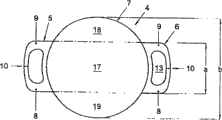
Figure 18 is a lenticular plan view from above as shown in Figure 2;
Figure 19 is the plan view from above according to lenticular the 3rd embodiment of the present invention;
Figure 20 is the plan view from above that as shown in Figure 7 crystalline lens comprises a tactile part;
Figure 21 is according to the of the present invention the lenticular the 4th and the fragmentary top plan view of five embodiment;
Figure 22 is the cutaway view of the line XXII-XXII in Figure 21;
Figure 23 is according to the of the present invention the lenticular the 6th and the fragmentary top plan view of seven embodiment; And
Figure 24 is the cutaway view of the line XXIV-XXIV in Figure 23.
The specific embodiment
At first present invention is described with reference to Fig. 1 and 2, wherein shown first embodiment that transplants this lenticular apparatus according to crystalline lens of the present invention and being used to.The crystalline lens that is presented among Fig. 2 also is displayed among Figure 18.
Insertion apparatus 1 as illustrated in fig. 1 and 2 is used for intraocular lens 4 is inserted in the eyes by the otch on the cornea 20 (schematically being presented at Fig. 2).Insert that apparatus 1 has the elongated insertion parts 2 of stretching out from grip part 14 and in the hook portion 3 that crosses out from parts 2 of parts 2 ends.The intraocular lens 4 who uses apparatus 1 to transplant had the sense of touch 5,6 of stretching out from the relative side of intraocular lens 4 opticator 7.Opticator 7 is deformable.Sense of touch 5,6 is formed by a pair of arm 8,9 respectively, so that the arm 8 that is being positioned at clamping region, clamp iris tissue between 9 the opposed facing surface, sense of touch 5,6 is arranged to when intraocular lens 4 is in the transplanting state opticator 7 is supported on and is parallel to and near the position of preceding iris surface plane.In Fig. 2, a sense of touch 5 is positioned at the side of opticator 7 towards insertion parts 2 ends of apparatus 1, and another sense of touch 6 is positioned at the side of opticator 7 towards insertion parts 2 near-ends of apparatus 1.Sense of touch 5,6 is radially stretched out from opticator 7, when being in the transplanting state with convenient intraocular lens 4, keeps intraocular lens 4 that its opticator 7 is in substantially and the parallel position of preceding iris surface plane.Hole 13 is to be made by transparent deformable material by sense of touch 5,6 gauges and opticator 7.
When preparing to insert intraocular lens 4 in the eyes, intraocular lens 4 is in and makes the position of opticator 7 near insertion parts 2, and the end portion that is in away from the sense of touch 5 of opticator 7 is engaged by hook portion 3.Insertion parts 2 supports the intraocular lens by hook portion 3 engagements subsequently.
More specifically, intraocular lens 4 engages by wide 11,12 of end portion in position that lateral spacing is at least opened.This has stoped the inclination of intraocular lens 4 around insertion parts 2, thereby has improved before inserting and afterwards to the control in intraocular lens 4 orientation.This helps intraocular lens's insertion again and helps being avoided the intraocular lens to contact with sensitive organization in the eyes.Cause the intraocular lens supported to intraocular lens 4 in the support of lateral spacing open position, make the intraocular lens controlled fully substantially with respect to the position of insertion parts at least three positions.
The width of wide portion is preferably at least one millimeter.
According to this embodiment, wide 11,12 comprises the support smooth section (supportplateau) 12 that is close to hook portion 3, and this support smooth section 12 supports the intraocular lens 4 by hook portion 3 engagements.Provide the special advantage of the support smooth section that can have closure or open design to be, intraocular lens 4 can be held in place along insertion parts 2 at an easy rate.If intraocular lens 4 is positioned at insertion parts top, this effect can obtain by gravity.In addition or alternatively, viscoelastic fluid such as HPMC (hydroxypropyl emthylcellulose) or the transparent plastid of sodium (Sodiumhyaluron)-for example be injected into usually in the eyes with the sort of type of keeping anterior chamber's volume-can be applied in (preferably sufficiently) to intraocular lens 4 and/or insertion parts 2.This material causes intraocular lens 4 to adhere on the insertion parts 2, and if this material between wide 12 big relatively surface and intraocular lens 4 that forms by insertion parts 2, this adhesiving effect is especially effective.This material also forms the lubricant between intraocular lens 4 and the insertion parts 2, friction when on insertion parts 2, sliding between intraocular lens 4 and the insertion parts 2 to reduce intraocular lens 4, and reduce intraocular lens 4 and be damaged especially intraocular lens 4 opticator 7 impaired danger.
Therefore wide 12 of insertion parts 2 define a plane, intraocular lens 4 is held near next-door neighbour's hook portion 3 ground, this plane, makes that inserting apparatus before inserting intraocular lens 4 will be supported on parallel with wide 12 substantially well-controlled orientation reliably by the intraocular lens 4 that hook portion 3 engages.In this embodiment, wide 12 width approximately is 2 to 4 millimeters.
After intraocular lens 4 had entered eyes, wide 12 protection iris and natural lens (if applicable) were avoided the especially injury of sense of touch 5,6 of intraocular lens 4, and the risk that makes these interior tissues of causing eyes come to harm is low especially.
Preferably as shown in figure 18, firm relatively part has width a, and this width is to be parallel to by the supporting plane of sense of touch 5,6 qualifications and perpendicular to longitudinal direction to measure, and it is less than the width b of the opticator of measuring along equidirectional 7.The width a of the radial direction of stretching out perpendicular to sense of touch that tactile firm part has is less than 4mm, preferably less than 80% of the width b (measuring along equidirectional) of opticator, more preferably less than 60% of the width b of opticator.
When intraocular lens 4 was engaged by hook portion 3, the wide second portion 16 of hook portion 3 was engaged on sense of touch 5 and the insertion parts 2 lateral spacing position of opening along the longitudinal, thereby prevented that sense of touch 5 from tilting around the longitudinal axis of insertion parts 2.Because sense of touch 5 is firm relatively, the power that is applied in the sense of touch 5 by hook portion 3 is delivered to deformable opticator 7 effectively, and limits a zone 17 with sense of touch 5 vertical consistencies, is cancelled in the bending of this zone opticator 7.Therefore, if opticator 7 is before inserting eyes or be deformed during insertion, flexural deformation by major limitation to the side zones 18,19 that is positioned at central area 17 sides.Therefore, when the intraocular lens recovers its original shape again, the orientation of central area 17-and since the zone 17 of sense of touch 5,6 and opticator minimum bending therein along whole intraocular lens's 4 insertion parts 2 be held-be very predictable.Width according to the second portion 16 of the hook portion 3 of this embodiment is 1.5 to 2.5 millimeters.
The second portion 16 of hook portion 3 is formed by flat lip shape portion.Therefore, the end of insertion parts 2 is blunt nosed relatively, and this has reduced danger that ocular tissue is damaged.And this feature helps hook portion 3 to insert by the opening 13 that will be limited by the sense of touch 5 that hook portion 3 meshes, and hook portion 3 makes easily, for example by making sheet bending or passing through injection molding.
The first 15 of hook portion 3 extends along adterminal direction from the neighbouring part of insertion parts 2.This makes and for example by otch 20 hook portion 3 is taken out at an easy rate from opening 13 by recalling insertion parts 2 simply in a longitudinal direction backward after intraocular lens 4 has inserted eyes.The insertion parts longitudinal direction or at least the angle between the first of the part of its contiguous hook portion 3 and the hook portion 3 of stretching out from insertion parts can be for example be 70 ° of at least 20 ° or maximums.
According to this embodiment, insertion parts 2 is flat piece of being made by sheet material.This makes that insertion parts 2 can be with the plain mode manufacturing, and enough rigidity and pliabilities are provided, so that control and handle intraocular lens 4 only occupies the very little part of the cross section of otch 20 simultaneously in the process of intraocular lens 4 being inserted eyes.
Preferably as shown in Figure 1, the shoulder 21 of insertion parts 2 next-door neighbour hook portions 3 has the width bigger than hook portion 3.This can prevent to be slided in the grip part direction along insertion parts 2 by the intraocular lens 4 of hook portion 3 engagements of the insertion parts 2 of passing the opening 13 that sense of touch 5 limits.Shoulder 21 forms the end of the part of insertion parts 2, and therefore its width can be prevented from by opening 13 greater than the width of opening 13.
In Fig. 3, the insertion parts 102 of the insertion apparatus of demonstration has in abutting connection with narrow 122 of hook portion 103, and narrow 122 narrower than wide 112.Intraocular lens's opticator bent position when being arranged in the intraocular lens for narrow 122 and inserting eyes, the bending of narrow 122 pairs of opticators is disturbed very little and is occupied less space when wide such as narrow of fruit is the same with wide 112, thereby for stacking part acquisition space by the intraocular lens's of insertion parts engagement opticator.This further helps intraocular lens's opticator to pass through otch.
Shown in Figure 4 and 5, to insert apparatus and may further include the meshing part 223 that is positioned at insertion parts 202 1 sides, meshing part 223 and hook portion 203 are positioned at the same side of insertion parts 202.Meshing part 223 is suitable for meshing the intraocular lens's 204 who is meshed by hook portion 203 sense of touch 206 and stretches out away from hook portion 203 ground.Therefore, the sense of touch 206 that meshing part 223 can keep deviating from hook portion 203 (or deviate from by its engagement sense of touch 205) near or near insertion parts 202, thereby obtain the control more positive to intraocular lens 204.Insertion parts 202 according to this embodiment is formed by the flexible metal sheet, can deviate from insertion parts 223 at an easy rate and be bent.Move intraocular lens 204 by the longitudinal direction along insertion parts 202, meshing part can be slided in the opening 213 in the sense of touch 206 of meshing part 202 at an easy rate.Engagement between intraocular lens 204 and the hook portion 203 can form in advance, but also can form simultaneously or after this.When insertion parts 202 was allowed to bending backward, the arm of sense of touch 206 was maintained between insertion parts 202 and the meshing part 203.
In order to help intraocular lens 204 and meshing part 203 to throw off after intraocular lens 204 inserts eyes, meshing part 223 can lift to discharge by the sense of touch 206 of its engagement from insertion parts 202.For this reason, meshing part 223 can be for example on longitudinal direction 224 part along insertion parts removable, this part of insertion parts is extended at angle with respect to a part that is engaged the meshing part 223 in the zone that parts 223 keep in sense of touch 206.
Fig. 6 has shown the insertion parts 302 that is used to transplant another embodiment of lenticular insertion apparatus according to of the present invention.According to this embodiment, next-door neighbour's hook portion 303 and be in the same side of insertion parts 302 with hook portion 303, insertion parts 302 has a part that has the central area of stretching out.When opticator is forced through a narrow passage, for example during the otch in the eyes, the bending of intraocular lens's opticator is supported along predetermined direction in the central area of stretching out, and makes the side direction part of opticator towards insertion parts 302.Core is recessed can to obtain similar effect by making, but in the opposite direction.The side direction part of intraocular lens's opticator is impelled subsequently away from the insertion parts bending.
Fig. 7-9 has shown another embodiment of the present invention, wherein, insert apparatus also comprise a length than the length of insertion parts 402 little give inlet pipe 427.Have for inlet pipe 427 to be used for the intraocular lens's 404 that the part that receives insertion parts 402 and its sense of touch 405 meshed by hook portion 403 internal channel 428 and be used at the infundibulum 429 that enters to the process compression intraocular lens 404 of inlet pipe 427.Infundibulum 429 is releasably attached to the end to inlet pipe 427.
During use, intraocular lens 404 at first with from giving hook portion 403 engagements of the insertion parts 402 that inlet pipe 427 and infundibulum 429 stretch out.Subsequently, intraocular lens 404 is drawn into in the inlet pipe 427, for this reason, can apply swabbing action or use pull bar 430 shown in Fig. 7 and 8 at the near-end of giving inlet pipe 427, pull bar 430 has hook portion 431 and its cross section less than the internal cross section of giving inlet pipe 427 at its end.Because hook portion 403 is engaged on the intraocular lens 404, insertion parts 402 is along with intraocular lens 404 is transferred.The width of passage 428 of giving inlet pipe 427 is less than the width of intraocular lens 404 opticator, and opticator must be out of shape to adapt to the width of passage 428 in the process of admission passage 428.Help the opticator distortion by infundibulum 429.After the intraocular lens has been drawn into passage 428, infundibulum 429 is taken off from giving inlet pipe 427, to reduce the cross section that apparatus will be inserted through the part of the otch on the cornea.Subsequently, be inserted in the eyes for the end of inlet pipe 427 by the otch on the cornea.Then, insertion parts 402 is pushed outwards, so that the intraocular lens is by from releasing and discharge eyes from the end of giving inlet pipe 427 for inlet pipe 427.Although use during by the otch on the cornea distortion of keeping the intraocular lens to inlet pipe must cause the part of the effective cross section of otch to be given inlet pipe occupied the intraocular lens, but it has also produced advantage, that is, can apply big relatively power is out of shape the intraocular lens and being used to of being applied is out of shape the intraocular lens power and can not act on tissue around the otch on the cornea.Also can keep by its otch that is inserted into and to be positioned at its front near intraocular lenss, and subsequently intraocular lens 404 be displaced from give inlet pipe and pass through otch to inlet pipe 427.Intraocular lens 404 is left to after inlet pipe 427 ends by force by inserting apparatus 402, the intraocular lens by from give inlet pipe 427 discharge after its temporary transient engagement that keeps with the insertion apparatus.Therefore, at least when the intraocular lens begins to recover its original shape, intraocular lens 404 is engaged on the insertion parts 402, thereby, when intraocular lens 404 intraocular lens's when discharging to inlet pipe position keeps controlled, intraocular lens's 404 arrival are not wished the position that arrives or are reduced widely by the danger of intraocular lens's 404 uncontrolled contact inside ofeye tissues the intraocular lens is released after.
Preferably as shown in Figure 9, have elongated cross sections for inlet pipe 427.This makes intraocular lens 404 size to reduce significantly in the direction that is transverse to inlet pipe extends and the intraocular lens is inserted into, and elongated cross sections can relatively easily be inserted into passes through linear cuts.
Figure 10-13 has shown the end that comprises to another embodiment of the insertion apparatus of inlet pipe 527, and intraocular lens 504 is inserted in in the inlet pipe 527.In Figure 10 and 11, intraocular lens 504 is shown the position that is in infundibulum 529 fronts, is inserted into parts 502 this position intraocular lens and maintains.Infundibulum 529 forms with giving inlet pipe 527.In Figure 12 and 13, shown by the insertion parts 502 that promotes its hook portion 503 engagement intraocular lenss 504 to be introduced into to the intraocular lens after the inlet pipe 527 504 through the narrowest part that infundibulum 529 enters to inlet pipe 527 along arrow 532 directions.Under the state shown in Figure 12 and 13, intraocular lens 504 prepares to be used for inserting.This can be by inserting in the otch on the eyes cornea away from the end of infundibulum 529 and further subsequently intraocular lens 504 be finished from pull out for inlet pipe 527 away from the end of infundibulum 529 by giving inlet pipe 527 by move insertion parts 502 along arrow 532 directions to inlet pipe 527.Intraocular lens 504 from giving inlet pipe 527 and displaced and during by otch, also can will and being positioned at its front by its otch that is inserted into remaining close to the intraocular lens for inlet pipe 527.By after the otch, intraocular lens 504 launches subsequently at it.
Figure 14-17 has shown intraocular lens 604 and has inserted the end portion of an embodiment of apparatus that it also comprises a medicated cap 627.The width of medicated cap 627 is suitable for having the part of the reception insertion parts 602 contiguous hook portions 603 of certain interval.When medicated cap 627 when the longitudinal direction (shown in the arrow among Figure 14) perpendicular to insertion parts 602 is positioned on the insertion parts 602, by the side direction part of the intraocular lens's 604 of insertion parts 602 engagements opticator lateral edges bent around in insertion parts 602.After medicated cap 627 was arranged on intraocular lens 604 and the insertion parts 602, the intraocular lens 604 who is remained on deformation state by medicated cap 627 was inserted in the eyes.Then, medicated cap 627 is retracted from eyes, thereby discharges intraocular lens 604.At last, insertion parts also is pulled from eyes, and the intraocular lens is fixed on the iris in eyes.
Then, will describe and discuss the details of the intraocular lens shown in intraocular lens shown in Figure 180 and Figure 19 subsequently-24.The size in the intraocular lens's shown in Figure 180 4 who is parallel to the plane and measures perpendicular to radial direction hole 13 is greater than the size in the hole of measuring along radial direction 13.This has limited the degree of freedom of intraocular lens 4 around first's 15 rotations of hook portion 3 basically, makes intraocular lens 4 by hook portion 3 engagements remain on reliably substantially and insertion parts 2 positions aligning.
Shown intraocular lens 704 in Figure 19, its sense of touch 706 comprises the eyelet 733 outside the hole 713 of removing between the arm 708,709.Eyelet 733 is suitable for by such as the hook portion of hook portion 431 engagement and littler than hole 713.Preferably, the diameter of eyelet 733 is less than 1mm.Another feature of intraocular lens shown in Figure 19 is that in the arm 708,709 is thicker than another.This provides the space for other eyelet 733.Arm another advantage thicker than another arm is, a slice (plea) iris tissue is being introduced in the process of the clamping slit between the clamp arm, basically have only thinner brachiocylloosis, make another arm to be held, thereby accurately intraocular lens 704 is held in place.But, be used for also can being arranged on symmetric sense of touch 806 as shown in figure 20 by the eyelet 833 that the hook portion such as hook portion 431 meshes.
Shown a kind of intraocular lens in Figure 21 and 22, for the purpose of illustrative, it has two different senses of touch.In the reality, usually preferably has identical sense of touch in intraocular lens's both sides.As shown in figure 22, sense of touch 905,1005 is stretched out backward from opticator 907.Each hole 913,1013 is positioned near a part 935,1035 position backward of opticator 907 away from the part 934,1034 of opticator 907.This helps hook portion 3 and meshing part 223 to insert in the hole, because this can make them insert along the planar direction that is arranged essentially parallel to opticator 907.Sense of touch 905,1005 from opticator 907 stretch out backward also help when transplanting state, keeping opticator in the past the iris surface plane be lifted.This is favourable for making current by pupil.
For the sense of touch 905 of making by firm relatively material, 1005 and the opticator 907 made by the material of relative resilient between obtain firm joint, keep simultaneously by sense of touch 905,1005 and opticator between the zone that occupies of connection narrower, to avoid the optics obstacle and to obtain the intraocular lens of Compact Design, sense of touch 905,1005 is glued on the opticator.In this embodiment, bonding realizes by binding agent, but directly bonding for example obtains around insert in the injection molding process.Binding agent is positioned in the groove 940,1040 on the opticator 907 at least in part.In addition or alternatively, if sense of touch and opticator are correspondingly designed, also binding agent can be arranged in the groove in the sense of touch.
For help that sense of touch 905,1005 is installed and increase sense of touch 905,1005 and opticator 907 between bonding strength, flange 943,1043 is set.Flange 943 is integral with opticator 907, and the spill rear surface 937 of opticator extends to the flange outer end.As shown in figure 22, this architectural feature is formed on the opticator 907 along the side door 951 of the peripheral part of the opticator between two senses of touch.
Shown in Figure 23 and 24, the different senses of touch 1105,1205 that are positioned on intraocular lens's 1104 opposite sides have been shown.In this intraocular lens, sense of touch 1105,1205 also be by adhesives to opticator 1107.In this intraocular lens 1104, opticator 1107 and sense of touch 1105,1205 have proximal part 1142,1242 respectively, and they are peripherally being surrounded by the localization part 1146,1246 of flange 1143,1243.Binding agent is positioned between sense of touch 1105,1205 and the localization part 1146,1246 at least in part, thereby obtains to connect especially reliably.Flange 1143,1243 forms with opticator 1107, and extend along the rear surface part of flange the spill rear surface of opticator.As shown in figure 24, this architectural feature is formed on the opticator 1107 along the side door 1151,1251 of the peripheral part of the opticator between two senses of touch.
A characteristic feature of sense of touch 1105 is that it comprises the sidewise hole 1147 that is positioned on the opticator 1107, outside the hole 1113 that is limited by clamp arm 1108,1109.Hole 1147 is communicated with the cheese space that spill rear surface by opticator 1107 limits on the opticator 1107.Thereby the special current of having guaranteed reliably in pupil region.For passage being provided for the current in pupil region, lateral port 1148 interconnects the sidewise hole 1147 of opticator 1107 with the hole 1113 that is limited by clamp arm 1108,1109.Can realize intraocular lens 1104 especially stably is fixed on the iris front surface, limit a stayed surface 1149 with the parallel substantially plane 1136 of the optical flat 1150 of opticator 1107 because sense of touch 1105 also has.
According to intraocular lens of the present invention, insert apparatus and parts and preferably provide kit utility as eye therapy with compound mode, it comprises apparatus and intraocular lens, apparatus is dimensioned to can be in Kong Zhongyu intraocular lens's firm part engagement.Therefore the apparatus that can guarantee to be used to transplant the intraocular lens automatically can be assembled to the intraocular lens.
In order to help to transplant, the intraocular lens preferably be provided as by apparatus or at least its insertion parts remain on the position of pre-installation, and with the apparatus in common package or at least insertion parts be sterilized.Therefore, do not need to apparatus or at least insertion parts carry out independent sterilization, and reduced the intraocular lens is installed to intraocular lens and the contaminated risk of insertion parts in the process of insertion parts.In order to reduce refuse, the insertion parts of use can reclaim to be cleaned and with other transplanted intraocular lens being repacked and sterilizing.
Claims (22)
1, a kind of being used for intraocular lens (4; 204; 504; 604; 704; 904; 1104) the insertion apparatus in the insertion eyes comprises being elongated insertion parts (2 along the longitudinal; 202; 302; 402; 502; 602) and be positioned at described insertion parts (2; 202; 302; 402; 502; 602) Mo Duan hook portion (3; 103; 203; 303; 403; 503; 603), described hook portion is from described insertion parts (2; 202; 302; 402; 502; 602) laterally stretch out described insertion parts (2; 202; 302; 402; 502; 602) described end comprises first wide part (12), and the width that first wide part has is suitable for meshing described intraocular lens (4 in the position that lateral spacing is at least opened; 204; 504; 604; 704; 904; 1104); It is characterized in that described hook portion (3; 103; 203; 303; 403; 503; 603) comprise and cross described vertical and described width from described insertion parts (2; 202; 302; 402; 502; 602) first that neighbouring part stretches out (15) and the second portion (16) that stretches out to hook portion from described first (15) terminally, described hook portion (3; 103; 203; 303; 403; 503; The structure of described second portion (16) 603) comprises second wide part (11), is used for from intraocular lens (4; 204; 504; 604; 704; 904; 1104) opticator (7; 607; 907; 1107) mesh intraocular lens (4 to the intraocular lens terminally; 204; 504; 604; 704; 904; 1104) sense of touch (5,6; 205,206; 405,406,706; 806; 905; 1005; 1105; 1205).
2, insertion apparatus as claimed in claim 1 is characterized in that, described first wide part comprises the described hook portion (3 of next-door neighbour; 103; 203; 303; 403; 503; 603) support smooth section (12; 112), be used for supporting by described hook portion (3; 103; 203; 303; 403; 503; 603) Nie He a intraocular lens (4; 204; 504; 604; 704; 904; 1104).
3, insertion apparatus as claimed in claim 1 or 2 is characterized in that, described hook portion (3; 103; 203; 303; 403; 503; 603) described second portion (16) is to be formed by the lip shape portion that sheet material is made.
4, insertion apparatus as claimed in claim 1 or 2 is characterized in that, described hook portion (3; 103; 203; 303; 403; 503; The structure of described first (15) 603) is from described insertion parts (2; 202; 302; 402; 502; 602) neighbouring part extends towards the hook portion end direction.
5, insertion apparatus as claimed in claim 1 or 2 is characterized in that, described first wide part (12) has at least 1 millimeter width.
6, insertion apparatus as claimed in claim 1 or 2 is characterized in that, described insertion parts (2; 202; 302; 402; 502; 602) comprise the flat piece that sheet material is made.
7, insertion apparatus as claimed in claim 1 or 2 is characterized in that, near described hook portion (3; 103; 203; 303; 403; 503; 603) described insertion parts (2; 202; 302; 402; 502; 602) width that at least one shoulder (21) has is greater than described hook portion (3; 103; 203; 303; 403; 503; 603) structure width.
8, insertion apparatus as claimed in claim 1 or 2 is characterized in that, described insertion parts (202; 502; 602) has the described hook portion (203 of next-door neighbour; 503; 603) narrow (122) of structure, described narrow (122) are narrower than described first wide part.
9, insertion apparatus as claimed in claim 1 or 2, it is characterized in that, described insertion parts (302) has to have stretches out or the part of recessed central area, and stretch out or the part of recessed central area is close to the structure of described hook portion (303) and is in the same sides of insertion parts (302) with described hook portion (303) described having.
10, insertion apparatus as claimed in claim 1 or 2, it is characterized in that, also comprise the meshing part (223) that is positioned at described insertion parts (202) one sides, described meshing part (223) and described hook portion (203) are in the same side of described insertion parts (202), described meshing part (223) is suitable for engagement by the sense of touch (206) in the sense of touch of described hook portion (203) engagement, and deviates from described hook portion (203) and stretch out.
11, insertion apparatus as claimed in claim 1 or 2 is characterized in that, also comprises to inlet pipe (427; 527), its length is less than having described hook portion (403; 503) described insertion parts (402; 502) length, the described inlet pipe (427 of giving; 527) have and be used to receive described insertion parts (402; 502) a part and by described hook portion (403; 503) Nie He intraocular lens (404; 504) internal channel (428; 528) and be used for intraocular lens (404; 504) enter to inlet pipe (427; 527) compress intraocular lens (404 in the process; 504) infundibulum (429; 529).
12, insertion apparatus as claimed in claim 11 is characterized in that, also comprises pull bar (430), and described pull bar has the hook portion (431) of stretching out from described pull bar (430) end, and the cross section of described pull bar is less than described internal cross section of giving inlet pipe (427).
13, insertion apparatus as claimed in claim 12 is characterized in that, infundibulum (429) can be from giving inlet pipe (427) dismounting.
14, insertion apparatus as claimed in claim 11 is characterized in that, the described inlet pipe (428) of giving has elongated cross sections.
15, insertion apparatus as claimed in claim 1 or 2, it is characterized in that, also comprise a medicated cap (627), the width that described medicated cap has is suitable for having the part of the contiguous hook portion of reception insertion parts (602) (603) in gap, with convenient medicated cap (627) on lateral is positioned at insertion parts (602) time, will be folded on the part of the contiguous hook portion of described insertion parts (602) (603) by the intraocular lens's (604) of insertion parts (602) engagement opticator (607) marginal portion.
16, a kind ofly be used to prepare intraocular lens (4; 204; 504; 604; 704; 904; 1104) to insert the method in the eyes, comprising:
A kind of intraocular lens (4 is provided; 204; 504; 604; 704; 904; 1104), described intraocular lens has the opticator of being made by transparent material (7; 607; 907; 1107); From opticator (7; 607; 907; 1107) radially-protruding at least one sense of touch (5,6; 205,206; 405,406,706; 806; 905; 1005; 1105; 1205), be used for opticator (7; 607; 907; 1107) be supported on and be parallel to plane (936; 1136) position; And by described sense of touch (5,6; 205,206; 405,406,706; 806; 905; 1005; 1105; 1205) at least one hole (13 of Xian Dinging; 213; 713; 913; 1013; 1113);
Be provided for intraocular lens (4; 204; 504; 604; 704; 904; 1104) the insertion apparatus in the insertion eyes, described insertion apparatus comprises being elongated insertion parts (2 along the longitudinal; 202; 302; 402; 502; 602) and be positioned at described insertion parts (2; 202; 302; 402; 502; 602) Mo Duan hook portion (3; 103; 203; 303; 403; 503; 603), described hook portion is from described insertion parts (2; 202; 302; 402; 502; 602) neighbouring part crosses and describedly vertically stretches out;
With described hook portion (3; 103; 203; 303; 403; 503; 603) be engaged to described sense of touch (5,6; 205,206; 405,406,706; 806; 905; 1005; 1105; 1205) on, described sense of touch (5,6; 205,206; 405,406,706; 806; 905; 1005; 1105; 1205) be located at described opticator (7; 607; 907; 1107) Mo Duan position;
Wherein, described intraocular lens (4; 204; 504; 604; 704; 904; 1104), mesh described intraocular lens (4 in the position that lateral spacing is at least opened by first wide of the end portion of described insertion parts part engagement; 204; 504; 604; 704; 904; 1104);
Described hook portion (3; 103; 203; 303; 403; 503; 603) comprise and cross described vertical and described width from described insertion parts (2; 202; 302; 402; 502; 602) first that neighbouring part stretches out (15) and the second portion (16) that stretches out to hook portion from described first (15) terminally;
Described intraocular lens (4; 204; 504; 604; 704; 904; 1104) be arranged to make described opticator (7; 607; 907; 1107) near described insertion parts (2; 202; 302; 402; 502; 602), described sense of touch (5,6; 205,206; 405,406,706; 806; 905; 1005; 1105; 1205) a part is positioned at described hook portion (3; 103; 203; 303; 403; 503; 603) under the described second portion (16), make described insertion parts (2; 202; 302; 402; 502; 602) support by described hook portion (3; 103; 203; 303; 403; 503; 603) Nie He described intraocular lens (4; 204; 504; 604; 704; 904; 1104); And
Described hook portion (3; 103; 203; 303; 403; 503; The structure of described second portion (16) 603) comprises second wide part (11).
17, method as claimed in claim 16 is characterized in that, described first wide part forms one and support smooth section, described intraocular lens (4; 204; 504; 604; 704; 904; 1104) be close to described hook portion (3; 103; 203; 303; 403; 503; 603) be positioned at the top of described support smooth section, make described insertion instrument supports by described hook portion (3; 103; 203; 303; 403; 503; 603) Nie He described intraocular lens (4; 204; 504; 604; 704; 904; 1104).
18, as claim 16 or 17 described methods, it is characterized in that described intraocular lens (4; 204; 504; 604; 704; 904; 1104) and described insertion apparatus be inserted into and have the giving in inlet pipe (427,527) or the medicated cap (627) of internal channel, and inserting in the described process of giving inlet pipe (427,527) or medicated cap (627) described opticator (7; 607; 907; 1107) be deformed along at least one direction.
19, method as claimed in claim 18 is characterized in that, as described intraocular lens (4; 204; 504; 604; 704; 904; 1104) and described insertion apparatus be inserted into describedly when giving in inlet pipe (427,527) or the medicated cap (627), described insertion apparatus meshes described intraocular lens (4; 204; 504; 604; 704; 904; 1104).
20, method as claimed in claim 18 is characterized in that, described opticator (7; 607; 907; 1107) marginal portion is given in inlet pipe (427,527) or the medicated cap (627) around described insertion parts (2 described; 202; 302; 402; 502; 602) a part is folded.
21, a kind of kit utility of eye therapy comprises the intraocular lens and as the arbitrary described insertion apparatus of claim 1-15;
Wherein, described intraocular lens comprises the opticator of being made by transparent deformable material (7; 607; 907; 1107); From opticator (7; 607; 907; 1107) radially-protruding at least one sense of touch (5,6; 205,206; 405,406,706; 806; 905; 1005; 1105; 1205), be used for opticator (7; 607; 907; 1107) be supported on parallel and near preceding iris surface plane (936; 1136) position; And by described sense of touch (5,6; 205,206; 405,406,706; 806; 905; 1005; 1105; 1205) at least one hole (13 of Xian Dinging; 213; 713; 913; 1013; 1113), wherein, described sense of touch (5,6; 205,206; 405,406,706; 806; 905; 1005; 1105; 1205) the firm part of at least one has than opticator (7; 607; 907; 1107) higher rigidity is to prevent that the intraocular lens is around the axis bending along described radial direction; At least described firm part has the width (a) that is parallel to described plane and measures perpendicular to described radial direction, and described width (a) is less than opticator (7; 607; 907; 1107) along the size (b) of described width;
Described hook portion (3; 103; 203; 303; 403; 503; 603) be suitable in described hole (13; 213; 713; 913; 1013; 1113) the described intraocular lens (4 of engagement in; 204; 504; 604; 704; 904; 1104) described firm part;
Described intraocular lens (4; 204; 504; 604; 704; 904; 1104) be suitable for being arranged to make described opticator (7; 607; 907; 1107) near described insertion parts (2; 202; 302; 402; 502; 602), described sense of touch (5,6; 205,206; 405,406,706; 806; 905; 1005; 1105; 1205) a part is positioned at described hook portion (3; 103; 203; 303; 403; 503; 603) under the described second portion (16), make described insertion parts (2; 202; 302; 402; 502; 602) support by described hook portion (3; 103; 203; 303; 403; 503; 603) Nie He described intraocular lens (4; 204; 504; 604; 704; 904; 1104); And
Described hook portion (3; 103; 203; 303; 403; 503; The structure of described second portion (16) 603) comprises second wide part (11).
22, the kit utility of eye therapy as claimed in claim 21 is characterized in that, described intraocular lens (4; 204; 504; 604; 704; 904; 1104) maintained by described insertion apparatus, and described intraocular lens (4; 204; 504; 604; 704; 904; 1104) and described insertion apparatus be packaged in the common package.
Applications Claiming Priority (2)
| Application Number | Priority Date | Filing Date | Title |
|---|---|---|---|
| EP02076022.9 | 2002-03-15 | ||
| EP20020076022 EP1344503B1 (en) | 2002-03-15 | 2002-03-15 | Intraocular lens |
Related Parent Applications (1)
| Application Number | Title | Priority Date | Filing Date |
|---|---|---|---|
| CNB031206220A Division CN100360096C (en) | 2002-03-15 | 2003-03-17 | Artificial crystalline for transplanting in eyes and appliance and method for inserting such crystalline |
Publications (2)
| Publication Number | Publication Date |
|---|---|
| CN1954790A CN1954790A (en) | 2007-05-02 |
| CN100551344C true CN100551344C (en) | 2009-10-21 |
Family
ID=27763414
Family Applications (2)
| Application Number | Title | Priority Date | Filing Date |
|---|---|---|---|
| CNB031206220A Expired - Lifetime CN100360096C (en) | 2002-03-15 | 2003-03-17 | Artificial crystalline for transplanting in eyes and appliance and method for inserting such crystalline |
| CNB2006101219098A Expired - Lifetime CN100551344C (en) | 2002-03-15 | 2003-03-17 | The intraocular lens is inserted the insertion apparatus in the eyes and prepares intraocular lens's the method and the kit utility of eye therapy |
Family Applications Before (1)
| Application Number | Title | Priority Date | Filing Date |
|---|---|---|---|
| CNB031206220A Expired - Lifetime CN100360096C (en) | 2002-03-15 | 2003-03-17 | Artificial crystalline for transplanting in eyes and appliance and method for inserting such crystalline |
Country Status (9)
| Country | Link |
|---|---|
| EP (3) | EP1593355B1 (en) |
| JP (2) | JP4053908B2 (en) |
| CN (2) | CN100360096C (en) |
| AT (1) | ATE530144T1 (en) |
| AU (2) | AU2003201012B2 (en) |
| CA (1) | CA2422167C (en) |
| ES (2) | ES2374268T3 (en) |
| PT (2) | PT1344503E (en) |
| ZA (1) | ZA200302055B (en) |
Families Citing this family (15)
| Publication number | Priority date | Publication date | Assignee | Title |
|---|---|---|---|---|
| NL1029403C2 (en) * | 2005-07-01 | 2007-01-04 | Medical Device Production B V | Multi focal intraoccular lens, has lens part with two optical fields and deformable and non deformable haptics |
| JP4727497B2 (en) * | 2006-05-17 | 2011-07-20 | スター・ジャパン株式会社 | Lens insertion device for intraocular insertion |
| US7879090B2 (en) | 2006-12-13 | 2011-02-01 | Bausch & Lomb Incorporated | Intraocular lens injector apparatus and methods of use |
| JP5465966B2 (en) * | 2009-09-29 | 2014-04-09 | 株式会社ニデック | Intraocular lens insertion system for phakic lens |
| DK2854708T3 (en) | 2012-06-04 | 2017-01-30 | Alcon Pharmaceuticals Ltd | DEVICE FOR INSTALLING AN INTRAOCULAR LENS AND PROCEDURE FOR EXTING AN INTRAOCULAR LENS FROM A PATTERN |
| RU2531464C1 (en) * | 2013-08-02 | 2014-10-20 | федеральное государственное бюджетное учреждение "Межотраслевой научно-технический комплекс "Микрохирургия глаза" имени академика С.Н. Федорова" Министерства здравоохранения Российской Федерации | Intraocular lens |
| EP3042634B1 (en) * | 2015-01-06 | 2017-09-27 | Infinitevision Optics | Multicomponent intraocular lens |
| US10588780B2 (en) | 2015-03-04 | 2020-03-17 | Alcon Inc. | Intraocular lens injector |
| US10172706B2 (en) | 2015-10-31 | 2019-01-08 | Novartis Ag | Intraocular lens inserter |
| DE102015224140B3 (en) | 2015-12-03 | 2017-04-20 | Carl Zeiss Meditec Ag | Intraocular lens with stiffened feel |
| US10568735B2 (en) | 2017-01-13 | 2020-02-25 | Alcon Inc. | Intraocular lens injector |
| US11000367B2 (en) | 2017-01-13 | 2021-05-11 | Alcon Inc. | Intraocular lens injector |
| DE102018110194A1 (en) | 2017-04-27 | 2018-10-31 | Klaus Nordmann | eye lens |
| NL2026797B1 (en) | 2020-10-30 | 2022-06-24 | Ophtec Bv | INTRAOCULAR LENS, INSERTION TOOLS THEREOF, ASSEMBLY PROVIDED THEREOF, AND PROCEDURE FOR MANUFACTURING |
| JP6943519B1 (en) * | 2021-05-28 | 2021-10-06 | 株式会社中京メディカル | Intraocular lens mounting device |
Family Cites Families (19)
| Publication number | Priority date | Publication date | Assignee | Title |
|---|---|---|---|---|
| US3913148A (en) * | 1974-12-26 | 1975-10-21 | Ernst W Potthast | Intraocular lens apparatus |
| US4122556A (en) * | 1977-03-23 | 1978-10-31 | Stanley Poler | Intra-ocular lens |
| US4143427A (en) * | 1977-06-10 | 1979-03-13 | Anis Aziz Y | Method and apparatus for accomplishing aphakic correction |
| DE3119002A1 (en) * | 1981-05-13 | 1982-12-02 | INPROHOLD Establishment, 9490 Vaduz | REAR CHAMBER IMPLANTATION LENS |
| US4573998A (en) | 1982-02-05 | 1986-03-04 | Staar Surgical Co. | Methods for implantation of deformable intraocular lenses |
| FR2538697B1 (en) * | 1982-12-30 | 1985-09-13 | Guerin Daniel | IMPLANT HOLDER PLIERS |
| US4560383A (en) * | 1983-10-27 | 1985-12-24 | Leiske Larry G | Anterior chamber intraocular lens |
| US4704123A (en) * | 1986-07-02 | 1987-11-03 | Iolab Corporation | Soft intraocular lens |
| US4880000A (en) * | 1987-12-15 | 1989-11-14 | Iolab Corporation | Lens insertion instrument |
| US5047051A (en) | 1990-04-27 | 1991-09-10 | Cumming J Stuart | Intraocular lens with haptic anchor plate |
| US5192319A (en) | 1991-05-20 | 1993-03-09 | Worst Jan G F | Intraocular refractive lens |
| US5147395A (en) | 1991-07-16 | 1992-09-15 | Allergan Inc. | Small incision endocapsulator IOL |
| WO1995013766A1 (en) | 1993-11-18 | 1995-05-26 | Allergan, Inc. | Deformable lens insertion apparatus |
| WO1995021594A1 (en) | 1994-02-09 | 1995-08-17 | Kabi Pharmacia Ophthalmics, Inc. | Rapid implantation of shape transformable optical lenses |
| GB9520457D0 (en) | 1995-10-06 | 1995-12-06 | Rayner Intraocular Llenses Lim | Intraocular lenses |
| FR2749161B1 (en) * | 1996-05-31 | 1998-11-06 | Ioltechnologie Production | IMPLANT FORMING INTRAOCULAR LENS FOR POSTERIOR CHAMBER |
| US5843187A (en) | 1997-08-06 | 1998-12-01 | Bayers; Jon H. | Insertable intraocular lens |
| FR2789890B1 (en) * | 1999-02-22 | 2002-01-18 | Lab Contactologie Appl Lca | DEVICE FOR INJECTING AN INTRAOCULAR LENS IN FLEXIBLE MATERIAL |
| US6461384B1 (en) * | 1999-06-17 | 2002-10-08 | Bausch & Lomb Incorporated | Intraocular lenses |
-
2002
- 2002-03-15 EP EP20050076710 patent/EP1593355B1/en not_active Expired - Lifetime
- 2002-03-15 ES ES02076022T patent/ES2374268T3/en not_active Expired - Lifetime
- 2002-03-15 ES ES05076710.2T patent/ES2483900T3/en not_active Expired - Lifetime
- 2002-03-15 EP EP20100186118 patent/EP2266505A3/en not_active Withdrawn
- 2002-03-15 PT PT02076022T patent/PT1344503E/en unknown
- 2002-03-15 EP EP20020076022 patent/EP1344503B1/en not_active Expired - Lifetime
- 2002-03-15 AT AT02076022T patent/ATE530144T1/en active
- 2002-03-15 PT PT05076710T patent/PT1593355E/en unknown
-
2003
- 2003-03-13 ZA ZA200302055A patent/ZA200302055B/en unknown
- 2003-03-14 AU AU2003201012A patent/AU2003201012B2/en not_active Expired
- 2003-03-14 CA CA 2422167 patent/CA2422167C/en not_active Expired - Lifetime
- 2003-03-17 CN CNB031206220A patent/CN100360096C/en not_active Expired - Lifetime
- 2003-03-17 JP JP2003071883A patent/JP4053908B2/en not_active Expired - Fee Related
- 2003-03-17 CN CNB2006101219098A patent/CN100551344C/en not_active Expired - Lifetime
-
2007
- 2007-08-22 JP JP2007215890A patent/JP4833170B2/en not_active Expired - Lifetime
-
2009
- 2009-02-13 AU AU2009200561A patent/AU2009200561B2/en not_active Expired
Also Published As
| Publication number | Publication date |
|---|---|
| CN100360096C (en) | 2008-01-09 |
| JP2004033731A (en) | 2004-02-05 |
| CA2422167C (en) | 2009-02-10 |
| JP2007325954A (en) | 2007-12-20 |
| AU2009200561A1 (en) | 2009-03-05 |
| AU2003201012B2 (en) | 2008-11-13 |
| CN1954790A (en) | 2007-05-02 |
| EP1593355A3 (en) | 2006-11-29 |
| JP4053908B2 (en) | 2008-02-27 |
| AU2009200561B2 (en) | 2011-09-01 |
| JP4833170B2 (en) | 2011-12-07 |
| EP1344503B1 (en) | 2011-10-26 |
| EP1344503A1 (en) | 2003-09-17 |
| ES2483900T3 (en) | 2014-08-08 |
| CA2422167A1 (en) | 2003-09-15 |
| EP1593355B1 (en) | 2014-06-18 |
| EP2266505A2 (en) | 2010-12-29 |
| PT1593355E (en) | 2014-09-03 |
| CN1446523A (en) | 2003-10-08 |
| EP2266505A3 (en) | 2011-03-30 |
| ATE530144T1 (en) | 2011-11-15 |
| PT1344503E (en) | 2012-02-01 |
| ES2374268T3 (en) | 2012-02-15 |
| EP1593355A2 (en) | 2005-11-09 |
| ZA200302055B (en) | 2003-09-15 |
| AU2003201012A1 (en) | 2003-10-09 |
Similar Documents
| Publication | Publication Date | Title |
|---|---|---|
| CN100551344C (en) | The intraocular lens is inserted the insertion apparatus in the eyes and prepares intraocular lens's the method and the kit utility of eye therapy | |
| US7416561B2 (en) | Intraocular lens for implantation in an eye and instrument and methods for insertion of such a lens | |
| JP2554844B2 (en) | Deformable intraocular lens | |
| EP2404573B1 (en) | Corneal implants | |
| US4485499A (en) | Intraocular posterior chamber lens | |
| US4888015A (en) | Method of replacing an eye lens | |
| CA1322627C (en) | Method and artificial intraocular lens device for the phakic treatment of myopia | |
| US9999497B2 (en) | Corneal implants and methods and systems for placement | |
| JPH0771566B2 (en) | Device for implanting a deformable intraocular lens structure | |
| CA2240146A1 (en) | Apparatus for lowering the intraocular pressure of an eye | |
| CA2466730A1 (en) | Flexible intra-ocular lens of variable focus | |
| US20230017116A1 (en) | Instruments and Methods for the Implantation of Cell-Seeded Ultra-thin Substrates | |
| US4547915A (en) | Intraocular posterior chamber lens | |
| US20060287655A1 (en) | Method for eye refractive surgery and device for implanting an intraocular refractive lens | |
| CN214908309U (en) | Intraocular tissue protection plate |
Legal Events
| Date | Code | Title | Description |
|---|---|---|---|
| C06 | Publication | ||
| PB01 | Publication | ||
| C10 | Entry into substantive examination | ||
| SE01 | Entry into force of request for substantive examination | ||
| C14 | Grant of patent or utility model | ||
| GR01 | Patent grant | ||
| CX01 | Expiry of patent term |
Granted publication date: 20091021 |
|
| CX01 | Expiry of patent term |