CN100521740C - Electronic equipment provided with battery check device - Google Patents
Electronic equipment provided with battery check device Download PDFInfo
- Publication number
- CN100521740C CN100521740C CNB2006101498927A CN200610149892A CN100521740C CN 100521740 C CN100521740 C CN 100521740C CN B2006101498927 A CNB2006101498927 A CN B2006101498927A CN 200610149892 A CN200610149892 A CN 200610149892A CN 100521740 C CN100521740 C CN 100521740C
- Authority
- CN
- China
- Prior art keywords
- fuel cell
- electronic equipment
- electric power
- time
- load
- Prior art date
- Legal status (The legal status is an assumption and is not a legal conclusion. Google has not performed a legal analysis and makes no representation as to the accuracy of the status listed.)
- Expired - Fee Related
Links
Images


Classifications
-
- H—ELECTRICITY
- H01—ELECTRIC ELEMENTS
- H01M—PROCESSES OR MEANS, e.g. BATTERIES, FOR THE DIRECT CONVERSION OF CHEMICAL ENERGY INTO ELECTRICAL ENERGY
- H01M8/00—Fuel cells; Manufacture thereof
- H01M8/04—Auxiliary arrangements, e.g. for control of pressure or for circulation of fluids
- H01M8/04298—Processes for controlling fuel cells or fuel cell systems
- H01M8/04313—Processes for controlling fuel cells or fuel cell systems characterised by the detection or assessment of variables; characterised by the detection or assessment of failure or abnormal function
- H01M8/04492—Humidity; Ambient humidity; Water content
- H01M8/04529—Humidity; Ambient humidity; Water content of the electrolyte
-
- H—ELECTRICITY
- H01—ELECTRIC ELEMENTS
- H01M—PROCESSES OR MEANS, e.g. BATTERIES, FOR THE DIRECT CONVERSION OF CHEMICAL ENERGY INTO ELECTRICAL ENERGY
- H01M8/00—Fuel cells; Manufacture thereof
- H01M8/04—Auxiliary arrangements, e.g. for control of pressure or for circulation of fluids
- H01M8/04082—Arrangements for control of reactant parameters, e.g. pressure or concentration
- H01M8/04089—Arrangements for control of reactant parameters, e.g. pressure or concentration of gaseous reactants
- H01M8/04119—Arrangements for control of reactant parameters, e.g. pressure or concentration of gaseous reactants with simultaneous supply or evacuation of electrolyte; Humidifying or dehumidifying
-
- H—ELECTRICITY
- H01—ELECTRIC ELEMENTS
- H01M—PROCESSES OR MEANS, e.g. BATTERIES, FOR THE DIRECT CONVERSION OF CHEMICAL ENERGY INTO ELECTRICAL ENERGY
- H01M8/00—Fuel cells; Manufacture thereof
- H01M8/04—Auxiliary arrangements, e.g. for control of pressure or for circulation of fluids
- H01M8/04223—Auxiliary arrangements, e.g. for control of pressure or for circulation of fluids during start-up or shut-down; Depolarisation or activation, e.g. purging; Means for short-circuiting defective fuel cells
- H01M8/04228—Auxiliary arrangements, e.g. for control of pressure or for circulation of fluids during start-up or shut-down; Depolarisation or activation, e.g. purging; Means for short-circuiting defective fuel cells during shut-down
-
- H—ELECTRICITY
- H01—ELECTRIC ELEMENTS
- H01M—PROCESSES OR MEANS, e.g. BATTERIES, FOR THE DIRECT CONVERSION OF CHEMICAL ENERGY INTO ELECTRICAL ENERGY
- H01M8/00—Fuel cells; Manufacture thereof
- H01M8/04—Auxiliary arrangements, e.g. for control of pressure or for circulation of fluids
- H01M8/04298—Processes for controlling fuel cells or fuel cell systems
- H01M8/043—Processes for controlling fuel cells or fuel cell systems applied during specific periods
- H01M8/04303—Processes for controlling fuel cells or fuel cell systems applied during specific periods applied during shut-down
-
- H—ELECTRICITY
- H01—ELECTRIC ELEMENTS
- H01M—PROCESSES OR MEANS, e.g. BATTERIES, FOR THE DIRECT CONVERSION OF CHEMICAL ENERGY INTO ELECTRICAL ENERGY
- H01M8/00—Fuel cells; Manufacture thereof
- H01M8/04—Auxiliary arrangements, e.g. for control of pressure or for circulation of fluids
- H01M8/04298—Processes for controlling fuel cells or fuel cell systems
- H01M8/04313—Processes for controlling fuel cells or fuel cell systems characterised by the detection or assessment of variables; characterised by the detection or assessment of failure or abnormal function
- H01M8/04537—Electric variables
- H01M8/04544—Voltage
- H01M8/04552—Voltage of the individual fuel cell
-
- H—ELECTRICITY
- H01—ELECTRIC ELEMENTS
- H01M—PROCESSES OR MEANS, e.g. BATTERIES, FOR THE DIRECT CONVERSION OF CHEMICAL ENERGY INTO ELECTRICAL ENERGY
- H01M8/00—Fuel cells; Manufacture thereof
- H01M8/04—Auxiliary arrangements, e.g. for control of pressure or for circulation of fluids
- H01M8/04298—Processes for controlling fuel cells or fuel cell systems
- H01M8/04313—Processes for controlling fuel cells or fuel cell systems characterised by the detection or assessment of variables; characterised by the detection or assessment of failure or abnormal function
- H01M8/04537—Electric variables
- H01M8/04544—Voltage
- H01M8/04559—Voltage of fuel cell stacks
-
- H—ELECTRICITY
- H01—ELECTRIC ELEMENTS
- H01M—PROCESSES OR MEANS, e.g. BATTERIES, FOR THE DIRECT CONVERSION OF CHEMICAL ENERGY INTO ELECTRICAL ENERGY
- H01M8/00—Fuel cells; Manufacture thereof
- H01M8/04—Auxiliary arrangements, e.g. for control of pressure or for circulation of fluids
- H01M8/04298—Processes for controlling fuel cells or fuel cell systems
- H01M8/04313—Processes for controlling fuel cells or fuel cell systems characterised by the detection or assessment of variables; characterised by the detection or assessment of failure or abnormal function
- H01M8/04664—Failure or abnormal function
- H01M8/04671—Failure or abnormal function of the individual fuel cell
-
- H—ELECTRICITY
- H01—ELECTRIC ELEMENTS
- H01M—PROCESSES OR MEANS, e.g. BATTERIES, FOR THE DIRECT CONVERSION OF CHEMICAL ENERGY INTO ELECTRICAL ENERGY
- H01M2250/00—Fuel cells for particular applications; Specific features of fuel cell system
- H01M2250/30—Fuel cells in portable systems, e.g. mobile phone, laptop
-
- Y—GENERAL TAGGING OF NEW TECHNOLOGICAL DEVELOPMENTS; GENERAL TAGGING OF CROSS-SECTIONAL TECHNOLOGIES SPANNING OVER SEVERAL SECTIONS OF THE IPC; TECHNICAL SUBJECTS COVERED BY FORMER USPC CROSS-REFERENCE ART COLLECTIONS [XRACs] AND DIGESTS
- Y02—TECHNOLOGIES OR APPLICATIONS FOR MITIGATION OR ADAPTATION AGAINST CLIMATE CHANGE
- Y02B—CLIMATE CHANGE MITIGATION TECHNOLOGIES RELATED TO BUILDINGS, e.g. HOUSING, HOUSE APPLIANCES OR RELATED END-USER APPLICATIONS
- Y02B90/00—Enabling technologies or technologies with a potential or indirect contribution to GHG emissions mitigation
- Y02B90/10—Applications of fuel cells in buildings
-
- Y—GENERAL TAGGING OF NEW TECHNOLOGICAL DEVELOPMENTS; GENERAL TAGGING OF CROSS-SECTIONAL TECHNOLOGIES SPANNING OVER SEVERAL SECTIONS OF THE IPC; TECHNICAL SUBJECTS COVERED BY FORMER USPC CROSS-REFERENCE ART COLLECTIONS [XRACs] AND DIGESTS
- Y02—TECHNOLOGIES OR APPLICATIONS FOR MITIGATION OR ADAPTATION AGAINST CLIMATE CHANGE
- Y02E—REDUCTION OF GREENHOUSE GAS [GHG] EMISSIONS, RELATED TO ENERGY GENERATION, TRANSMISSION OR DISTRIBUTION
- Y02E60/00—Enabling technologies; Technologies with a potential or indirect contribution to GHG emissions mitigation
- Y02E60/30—Hydrogen technology
- Y02E60/50—Fuel cells
Abstract
The invention provides an electronic equipment with battery check device and control method thereof. Immediately after a main switch is turned ON, a battery check is performed based on a first inhibit voltage lower than a second reference voltage which is an inhibit voltage level a predetermined time period after the main switch is turned ON, and therefore, even when the voltage is in a low state immediately after the main switch is turned ON, it is possible to activate a camera without an erroneous detection. Further, when the elapsed time from a time when the main switch is turned OFF to a time when tuned ON next time is relatively long, a solid high polymer film inside the fuel cell is assumed to be further dried, then the first inhibit voltage is changed, and therefore, even when the voltage fluctuates depending on the humidifying state immediately after the main switch is turned ON, an appropriate battery check can be performed.
Description
Technical field
The present invention relates to utilize the electronic equipment of the work about electric power that battery provides, relate in particular to electronic equipment with battery life testing fixture.
Background technology
Usually, there are various types of electronic equipments that utilize the work about electric power that battery provides.When especially providing electric power in can the electronic equipment of outdoor use, battery life is a subject matter.
Here, as the representative of electronic equipment that can outdoor use, will be example with the camera and be described.There is following known digital camera usually: the subject image by taking lens incident is carried out opto-electronic conversion by solid-state image pickups such as CCD, picture signal after this opto-electronic conversion is carried out A/D conversion so that it is recorded on the recording medium, and can be further by built-in LCD monitor display image.
Especially, for example, single mirror reversal photocamera (single lens reflex camera) with interchangeable taking lens need have with operability good like silver film (silver film) camera class and high-speed and continuous takes performance, take high-quality image, and have the wide brightness range of waiting to take subject.Because this reason needs to adopt to have a large amount of pixels and high-sensitive imaging apparatus.And, compare with the silver film camera, increase the large-scale circuit that imaging circuit, image processing circuit, image displaying circuit etc. are used a large amount of electronic units.
As a result, in the single mirror reversal photocamera of numeral, power consumption is big, and needs to provide the battery of enough energy.On the other hand, along with the development of camera to miniaturization and direction in light weight, more and more being difficult to for traditional primary cell or secondary cell provides sufficient energy for driving camera.
As the solution of this problem, small fuel cell has caused attention.Compare with traditional electricity generation system, the generating efficiency height of fuel cell, and also its discarded object is free of contamination.In addition, because the amount of the energy that every cube volume and weight provided almost is several times to tens times of conventional batteries, thereby we can say that fuel cell is useful as the power supply of miniaturized electronics.
Below, with the electricity generating principle in the explanation fuel cell.The fuel gas that fuel cell will comprise hydrogen offers fuel electrode, will wrap oxygen containing oxygen and offer oxygen electrode, thereby obtain electromotive force by the electrochemical reaction that takes place at two electrode places.The hydrogen that will offer fuel electrode by catalyst is separated into proton and electronics.Electronics after the separation moves to oxygen electrode by external circuit, and proton moves to oxygen electrode by solid polymer membrane (polyelectrolyte membrane).In oxygen electrode, in conjunction with proton, electronics and oxygen to generate water and carbon dioxide.
The electrochemical reaction that takes place on the fuel cell will be illustrated in.Formula (1) is illustrated in the reaction that fuel electrode takes place, and formula (2) is illustrated in the reaction that oxygen electrode takes place, and formula (3) is illustrated in the reaction that entire cell takes place.
H
2→2H
++2e
-...(1)
(1/2)O
2+2H
++2e
-→H
2O...(2)
H
2+(1/2)O
2→H
2O...(3)
Figure 16 A is the vertical view that an example of fuel cell is shown, and Figure 16 B is its front view.This fuel cell oxygen that negate should be used from extraneous air is as oxidant, and therefore, the upper surface of main frame 70, lower surface and length side surface are provided with the air vent hole 73 that is used to suck extraneous air.This air vent hole 73 is used for the water that generates is discharged as damp steam, and is used to discharge the heat that reaction produces.The short side surface of another of main frame 70 is provided with the electrode 72 that is used for power taking.
On the other hand, the inside of main frame 70 comprises battery part 71, and this battery part 71 comprises the battery more than, and this battery comprises fuel electrode 113, polyelectrolyte membrane 112, oxygen electrode 111.The inside of main frame 70 also comprises the fuel tank 76 that is used to store fuel, the fuel supply channel 75 that connects fuel tank 76 and each battery part 71 and the pressure sensor 77 that is used to measure fuel pressure.
Gou Zao cell of fuel cell has electromotive force and the about 300mA/cm of about 0.8V like this
2Current density, for example, specify the size of unit cells to be about 1.2cm * 2cm.When being connected in series 8 such cell of fuel cell, the output of entire cell is about 6.4V and 720mA, thereby produces the output of about 4.6W.In Figure 16 A and 16B, although respectively having two plywoods of the same area (laminated sheet) unit, utilization shows cell of fuel cell, the many plywoods that are connected in series as mentioned above can provide high voltage.
The hydrogen absorbed alloy alloy that can absorb hydrogen is filled in the inside of fuel tank 76.Because the withstand voltage of employed solid polymer membrane is 0.3~0.5MPa in the fuel cell, thereby need be to use this film in the scope of 0.1MPa at pressure reduction with extraneous air.
As having the hydrogen absorbed alloy alloy that the characteristic that is 0.2MPa is pressed in the release of hydrogen at normal temperatures, use LaNi
5Deng.Because LaNi
5Can absorb and discharge the hydrogen of 1.1wt%, thereby the amount that is stored in the hydrogen in the fuel tank 76 is 0.4g, and the energy that can generate electricity is about 11.3Whr, this energy is about four times of traditional lithium ion battery.On the other hand, when the hydrogen absorbing material that surpasses 0.2MPa is pressed in the release of using hydrogen at normal temperatures, need between fuel tank 76 and fuel electrode 113, pressure-reducing valve 78 be set.
The hydrogen that will be stored in the fuel tank 76 by fuel supply channel 75 offers fuel electrode 113.By air vent hole 73 extraneous air is offered oxygen electrode 111.The electricity that fuel cell produced is offered driven electronic equipment from electrode 72.
The part of each electrode contact water is insulated, and makes the electrode of fuel cell ought be recharged Shi Buhui conducting by the water that is used for electrolysis.A method of insulation is to utilize the part that does not contact with solid polymer membrane in the insulator-coating electrode.
In the fuel cell of constructing like this, when proton moves to oxygen electrode by solid polymer membrane, and if the solid polymer membrane drying, then the resistance value of solid polymer membrane increases.As a result, it is big that the power loss during generating becomes, and the generate output of polymer electrolyte fuel cell diminishes, and that is to say, the voltage step-down that can produce.
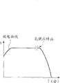
Thereby, after fuel cell has just begun power supply, the voltage step-down that can produce.Especially, in long-time untapped fuel cell, solid polymer membrane is drier, and the voltage that can produce when starting becomes lower.In Figure 17, show the example of the discharge curve of long-time untapped fuel cell.The longitudinal axis is represented voltage V, transverse axis express time T.In Figure 17, when starting, because solid polymer membrane is in drying regime, thereby the voltage step-down that can produce.After this, along with the carrying out of generating, the H that the reaction by formula (2) produces
2O gives solid polymer membrane humidification gradually, has reduced power loss, and discharge curve rises.Then, when the hydrogen supply stopped, discharge curve descended.
As the power-supply system of using this solid macromolecule membranous type fuel cell, be subjected to extensive concern for the method for the voltage step-down that the solid polymer membrane humidification can produce when preventing to start.For example, according to disclosed fuel-cell device in the Japanese kokai publication hei 09-213359 communique, at fuel battery inside configuration water-keeping material (water-holdingmaterial), the H that is produced during with output power
2O is stored in this water-keeping material.Then, when starting, allow hydrogen through this water-keeping material, to carry out humidification to solid polymer membrane.
In addition, according to the control method and the control device of disclosed fuel cell in TOHKEMY 2003-234116 communique, separate to be equipped with secondary cell and capacitor with fuel cell, and when starting, provide electric power from secondary cell and capacitor.
Incidentally, for the ease of using electronic equipment, need accurately know dump energy as the battery of power supply.Therefore, many electronic equipments are equipped with the remainder detecting device of battery capacity, and it is arranged such that and can the time carries out the voltage inspection (battery inspection) of internal battery in operation.
As the battery inspection, known following method: apply the load (that is to say) of the scheduled time to battery, thereby make cell voltage descend, and judge whether the cell voltage that descends is equal to or greater than predetermined level to the load energising.As carrying out the result that battery is checked, if cell voltage is equal to or greater than predetermined level, then process enters into next series of operations, and starts camera.On the contrary, if cell voltage is lower than predetermined level, then do not start camera.For example, when half push of release-push that carries out camera or main switch when (be used to begin photometry, range finding etc. and take the operation of preparing), perhaps (for example in the centre of the shooting sequence of camera, after shutter is finished the action of advancing, be about to carry out before the shutter charging), carry out this battery inspection.
In using the equipment of fuel cell as power supply, wherein this fuel cell uses the hydrogen that provides from hydrogen gas tank to act as a fuel, and when the surplus of hydrogen reduced, hydrogen pressure reduced.Therefore, there is a kind of technology as known technology, the hydrogen pressure that wherein detects the pressure in the hydrogen gas tank and discharge from hydrogen gas tank, thus carry out the detection of residual amount of hydrogen.
In addition, as the method for checking as the battery of the camera end of power supply at the fuel cell of fuel liquids such as utilization use methyl alcohol, the method (for example, referring to TOHKEMY 2003-295284 communique) of fuel liquid surplus is confirmed in existence by range estimation from the outside of camera.
In addition, the remainder detecting device of the battery that acts as a fuel has many based on the device that comes the technology of the surplus of counting cell capacity to propose according to primary quantity and use amount.For example, in Japanese kokai publication hei 11-230813 communique, disclose and a kind ofly come the device of the surplus of counting cell capacity according to initial fuel amount and use amount.
As mentioned above, in the electronic equipment of fuel cell is installed, need to carry out the battery inspection.In this case, for example, during disclosed surplus detects in Japanese kokai publication hei 11-230813 communique, need flowmeter and ammeter, this can cause cost rising etc.
Therefore, the load by battery being applied the scheduled time (that is to say, to the load energising) is to reduce cell voltage, and to judge whether be equal to or greater than predetermined level by the cell voltage that reduces to carry out the battery inspection be effective.If adopt this technology, then can make the simple in structure of battery, and can not hinder the miniaturization of electronic equipment, thereby may be controlled to this rising.
Yet as has been described, if use fuel cell, the voltage when starting is low, therefore, when the reference voltage when with startup compares, is judged as sometimes and forbids voltage level (dropping to the following voltage level of voltage that camera can be worked).That is to say, following problem occurred:, but be judged as and drive camera although the fact is in fact can drive camera.
Can expect compensating voltage when starting, make this class problem that do not take place by disclosed technology in Japanese kokai publication hei 09-213359 communique and TOHKEMY 2003-234116 communique.Yet, in Japanese kokai publication hei 09-213359 communique, in the disclosed fuel cell, need be used in the space of fuel battery inside configuration water-keeping material, this makes the further miniaturization of fuel cell become difficult.In addition, owing to need water-keeping material, thereby this can cause cost to rise.And in TOHKEMY 2003-234116 communique, in the control method and control device of disclosed fuel cell, needing secondary cell and capacitor dividually with fuel cell, this has not only hindered the miniaturization of camera, but also can cause cost to rise.
Summary of the invention
Consider that the problems referred to above have made the present invention, and an object of the present invention is to control cost not hindering electronics miniaturization rise in, make and can carry out suitable battery inspection.
Be characterised in that as the electronic equipment of one aspect of the present invention and comprise: fuel cell is used for providing electric power to described electronic equipment; Mains switch, be used for the described electronic equipment of subtend provide described fuel cell electric power beginning and stop to control; The battery inspection unit, it compares described fuel cell voltage and reference voltage; And control unit, be used for playing the elapsed time that begins once more till time when described electronic equipment provides the electric power of described fuel cell by described mains switch and measure from stop time when described electronic equipment provides the electric power of described fuel cell by described mains switch, and control described battery inspection unit, so that if the described elapsed time that measures is shorter than the scheduled time that sets in advance, then operate according to first reference voltage, if and the described elapsed time that measures be longer than the described scheduled time that sets in advance, then operate according to second reference voltage lower than described first reference voltage.
Be characterised in that as the present invention's electronic equipment on the other hand and comprise: fuel cell is used for providing electric power to described electronic equipment; Mains switch, be used for the described electronic equipment of subtend provide described fuel cell electric power beginning and stop to control; The battery inspection unit, its electric power output with described fuel cell is connected with load; And control unit, be used for playing the elapsed time that begins once more till time when described electronic equipment provides the electric power of described fuel cell by described mains switch and measure from stop time when described electronic equipment provides the electric power of described fuel cell by described mains switch, and control described battery inspection unit, so that if the described elapsed time that measures is shorter than the scheduled time that sets in advance, then utilize first load to operate, if and the described elapsed time that measures be longer than the described scheduled time that sets in advance, then utilize second load littler to operate than described first load.
Be characterised in that as the present invention's electronic equipment on the other hand and comprise: fuel cell is used for providing electric power to described electronic equipment; Mains switch, be used to control to described electronic equipment provide described fuel cell electric power beginning and stop; The battery inspection unit, it compares described fuel cell voltage and reference voltage; The Humidity Detection unit is used to detect the humidity of the solid polymer membrane of described fuel cell; And control unit, be used to control described battery inspection unit, if so that be higher than the predetermined moisture that sets in advance by the humidity of the detected described solid polymer membrane in described Humidity Detection unit, then operate according to first reference voltage, if and were lower than the described predetermined moisture that sets in advance by the humidity of the detected described solid polymer membrane in described Humidity Detection unit, would then operate according to second reference voltage lower than described first reference voltage.
Be characterised in that as the present invention's electronic equipment on the other hand and comprise: fuel cell is used for providing electric power to described electronic equipment; Mains switch, be used to control to described electronic equipment provide described fuel cell electric power beginning and stop; The battery inspection unit, its electric power output with described fuel cell is connected with load; The Humidity Detection unit is used to detect the humidity of the solid polymer membrane of described fuel cell; And control unit, be used to control described battery inspection unit, if so that be higher than the predetermined moisture that sets in advance by the humidity of the detected described solid polymer membrane in described Humidity Detection unit, then utilize first load to operate, if and were lower than the described predetermined moisture that sets in advance by the humidity of the detected described solid polymer membrane in described Humidity Detection unit, would then utilize second load littler to operate than described first load.
Be characterised in that as the present invention's electronic equipment on the other hand and comprise: fuel cell is used to provide electric power; And battery inspection unit, its predetermined amount of time after providing electric power by described fuel cell will be compared by described fuel cell voltage and the reference voltage that first load causes, and described fuel cell voltage and this reference voltage that will be caused by second load littler than described first load behind this predetermined amount of time compare.
Be characterised in that as the present invention's electronic equipment on the other hand and comprise: fuel cell is used to provide electric power; And the battery inspection unit, it will provide first voltage of detected described fuel cell behind the electric power and second voltage of detected described fuel cell of the scheduled time after detecting this first voltage to compare by described fuel cell.
Control method as the electronic equipment of one aspect of the present invention is the control method of following electronic equipment, this electronic equipment comprises the fuel cell that is used to provide electric power, this control method is characterised in that: battery is checked step, the predetermined amount of time that is used for after providing electric power by described fuel cell compares the described fuel cell voltage and first reference voltage, and behind this predetermined amount of time described fuel cell voltage and second reference voltage that is higher than described first reference voltage is compared.
Control method as the present invention's electronic equipment on the other hand is the control method of following electronic equipment, this electronic equipment comprises the fuel cell that is used to provide electric power, this control method is characterised in that: battery is checked step, the predetermined amount of time that is used for after providing electric power by described fuel cell will be compared by described fuel cell voltage and the reference voltage that first load causes, and described fuel cell voltage and this reference voltage that will be caused by second load littler than described first load behind this predetermined amount of time compare.
Control method as the electronic equipment of one aspect of the present invention is the control method of following electronic equipment, this electronic equipment comprises the fuel cell that is used to provide electric power, this control method is characterised in that: battery is checked step, is used for first voltage of detected described fuel cell after providing electric power by described fuel cell and second voltage that is detecting the detected described fuel cell of the scheduled time behind this first voltage are compared.
Computer program as one aspect of the invention is the computer program that is used to control electronic equipment, this electronic equipment comprises the fuel cell that is used to provide electric power, this computer program is characterised in that: allow computer to carry out battery and check step, this battery checks that the predetermined amount of time that step is used for after providing electric power by described fuel cell compares the described fuel cell voltage and first reference voltage, and behind this predetermined amount of time described fuel cell voltage and second reference voltage that is higher than described first reference voltage is compared.
As the present invention's computer program on the other hand is the computer program that is used to control electronic equipment, this electronic equipment comprises the fuel cell that is used to provide electric power, this computer program is characterised in that: allow computer to carry out battery and check step, this battery checks that the predetermined amount of time that step is used for after providing electric power by described fuel cell will be compared by described fuel cell voltage and the reference voltage that first load causes, and the described fuel cell voltage and the reference voltage that will be caused by second load littler than described first load behind this predetermined amount of time compare.
As the present invention's computer program on the other hand is the computer program that is used to control electronic equipment, this electronic equipment comprises the fuel cell that is used to provide electric power, this computer program is characterised in that: allow computer to carry out battery and check step, this battery inspection step is used for first voltage of detected described fuel cell after providing electric power by described fuel cell and second voltage of the detected described fuel cell of the scheduled time after detecting this first voltage compares.
By below in conjunction with the explanation of accompanying drawing to exemplary embodiments, further feature of the present invention will be apparent.
Description of drawings
Fig. 1 is the outside drawing of digital single mirror reversal photocamera of present embodiment;
Fig. 2 is the outside drawing of digital single mirror reversal photocamera of present embodiment;
Fig. 3 is made up of Fig. 3 A and 3B, and the block diagram of electronic structure of digital single mirror reversal photocamera of present embodiment is shown;
Fig. 4 A, 4B and 4C are the figure that the displaying contents of outer liquid crystal device 9 is shown;
Fig. 5 is the flow chart of processing operation that is used to explain digital single mirror reversal photocamera of first embodiment;
Fig. 6 is the flow chart of processing operation that is used to explain digital single mirror reversal photocamera of first embodiment;
Fig. 7 is the performance plot that an example of the discharge curve of fuel cell and the relation between the reference voltage is shown;
Fig. 8 is the flow chart of processing operation that is used to explain digital single mirror reversal photocamera of second embodiment;
Fig. 9 is the flow chart of processing operation that is used to explain digital single mirror reversal photocamera of second embodiment;
Figure 10 is the flow chart of processing operation that is used to explain digital single mirror reversal photocamera of the 3rd embodiment;
Figure 11 is the flow chart of processing operation that is used to explain digital single mirror reversal photocamera of the 3rd embodiment;
Figure 12 A and 12B are the performance plots that an example of the discharge curve of fuel cell and the relation between the reference voltage is shown;
Figure 13 is the flow chart of processing operation that is used to explain digital single mirror reversal photocamera of the 4th embodiment;
Figure 14 is the flow chart of processing operation that is used to explain digital single mirror reversal photocamera of the 4th embodiment;
Figure 15 is the flow chart of processing operation that is used to explain digital single mirror reversal photocamera of the 5th embodiment;
Figure 16 A and 16B are the figure that an example of fuel cell is shown;
Figure 17 is the performance plot of an example that the discharge curve of fuel cell is shown.
Embodiment
To describe the preferred embodiments of the present invention with reference to the accompanying drawings in detail.
First embodiment
Use electronic equipment of the present invention by illustrating as an example with the single mirror reversal photocamera of numeral.Fig. 1 and 2 is the outside drawing of digital single mirror reversal photocamera of present embodiment.Fig. 1 is the oblique view of seeing from the camera front side, and the state of taking the unit (not shown) of pulling down is shown.Fig. 2 is the oblique view of seeing from the camera rear side.Camera body frame 1 is provided with outstanding in front grip portions 1a, makes the user to stablize when taking and easily grips camera.
The mounting portion 2 that is arranged in the camera body frame 1 is zones that taking lens unit (not shown) removably is installed.The installation contact point 21 of mounting portion 2 transmits control signal, status signal, data-signal etc. between camera body and taking lens unit, and has the function of the electric current that all kinds voltage is provided.Installation contact point 21 can be arranged such that and not only realize telecommunication easily, but also realize optical communication, voice communication etc. easily.When dismounting taking lens unit, press the camera lens lock release button.
In camera body frame 1 inside, configuration has around the mirrored cabinet 5 of the shape of the light beam (light flux) that passes through the taking lens unit.Mirrored cabinet 5 comprise with being used for of keeping of 45 will be photoconduction by the taking lens unit to the fast return mirror 6 of pentaprism 22 (referring to Fig. 3 A and 3B) and view finder eyepiece window 18.
The upper surface mode of operation that the upper left side of camera (from the front) disposes release-push 7, main operation dial 8, LCD display floater (outer liquid crystal display device) 9 and camera system is provided with button 10.Release-push 7 is to be used to the starting switch that begins to take, and is configured to make when first pushes, and opens SW1 (7a), when second pushes, opens SW2 (7b).The mode of operation of main operation dial 8 when taking is provided with shutter speed and lens aperture value.LCD display floater 9 shows each mode of operation of camera.
The upper surface mode of operation is provided with button 10 and carries out following setting: be continuous shooting or the only shooting of a frame (the single bat) that begins by once pressing release-push 7, still begin self-timer mode etc., and it is provided with situation and is displayed on the LCD display floater 9.The back will describe (referring to Fig. 4 A, 4B and 4C) to content shown on the LCD display floater 9.
The center upper portion of camera disposes electronic flash (strobe) unit 11 that camera body is given prominence to, hot shoe groove 12 and the photoflash lamp contact point 13 that is used to install photoflash lamp.
The upper right side of camera (from the front) disposes screening-mode dial 14 is set.
The right flank of camera is provided with closable outside terminal lid 15.With the state that tegmentum 15 covers, configuration vision signal output plughole 16 and USB out connector 17 are as external interface.
The back side of camera disposes view finder eyepiece window 18 above optical axis center and color liquid crystal monitor 19 that can display image.Also dispose the main switch 43 and the child-operation dial 20 of the whole operation of the single mirror reversal photocamera of forbidden digit.Be configured in the booster action of child-operation dial 20 performances on color liquid crystal monitor 19 next doors to the function of main operation dial 8, for example, under the AE of camera pattern, child-operation dial 20 is used for by the suitable exposure that automatic exposure device calculated the exposure correction amount being set.Under manual mode, can shutter speed be set by main operation dial 8, and can the lens aperture value be set by child-operation dial 20.Child-operation dial 20 also is used as the demonstration choice device of photographic images shown in the color liquid crystal monitor 19.
Fig. 3 A and 3B are the block diagrams that the electronic structure of digital single mirror reversal photocamera is shown.In Fig. 3 A and 3B, Reference numeral 100 expression is included in the CPU (below be referred to as [MPU]) of the microcomputer in the camera body.Reference numeral 100a represents to be included in the EEPROM among the MPU 100, and its storage is about clock information and other photographing information of clock measuring circuit 109.
The focus detection sensor unit of Reference numeral 31 expression phase difference systems, although do not specifically illustrate, it is by being configured near object lens, transmitting mirror, secondary imaging camera lens, the aperture the imaging surface and comprising that the linear sensor etc. of a plurality of CCD constitutes.
By instruction, this view data can also not carried out any processing and be stored in the buffer storage 37 by Memory Controller 38 from MPU 100.Video processing circuit 104 also has the function that compressions such as carrying out JPEG is handled.In addition, under the situation of taking continuously, temporarily with image data storage in buffer storage 37, processing time if desired is long, then read untreated view data by Memory Controller 38, handle through the image processing and the compression of video processing circuit 104 then, thereby improve continuous shooting speed.The numbers of poles the earth of taking depends on the capacity of buffer storage 37 continuously.
When detecting power supply opening, begin from power supply 42 power supplies.
At this,, the displaying contents of outer liquid crystal device 9 is described with reference to Fig. 4 A~4C.Reference numeral 9a represents the demonstration of the state of screening-mode.Reference numeral 9b represents to show f-number by seven sections (seven segments).Reference numeral 9c represents to show shutter speed by seven sections.Reference numeral 9d represents to take the demonstration of quantity.Reference numeral 9e represents the demonstration of the state of AF pattern.Reference numeral 9f represents the demonstration of the state of drive pattern.Reference numeral 9g represents by a demonstration exposure correction amount, and a point represented for 1/3 step.Reference numeral 9j represents the demonstration of standard of the dump energy of power-supply battery 35.Reference numeral 9k represents the demonstration of the state of metering mode.
Then, with reference to Fig. 5~7, the processing operation of digital single mirror reversal photocamera of present embodiment is described.At step S101, MPU 100 judges by switch sensing circuit 105 whether main switch 43 closes.When judging main switch 43 and close, MPU 100 enters step S102.
At step S102, MPU 100 carries out and the communicating by letter of clock measuring circuit 109, and obtains current time T1, and after it being stored among the EEPROM 100a, enters step S103.
At step S103, MPU 100 judges by switch sensing circuit 105 whether main switch 43 is opened.When judging main switch 43 and open, MPU 100 enters step S104.
At step S104, MPU 100 carries out and the communicating by letter of clock measuring circuit 109, and obtains current time T2, and enters step S105.
At step S105, MPU 100 accesses the time T 1 that is stored among the EEPROM 100a, afterwards, enters step S106.At step S106, MPU 100 compares time T 1 and time T 2 to calculate elapsed time T3.
At step S107, reference time T0 and elapsed time T3 that MPU 100 will be stored among the EEPROM 100a in advance compare.
At step S107, when reference time T0 was longer than elapsed time T3, MPU entered step S108.At step S108, the inspection of beginning battery.In the present embodiment, carry out the battery inspection by so-called direct current pressure drop (direct current fall-of-potential) method, wherein cell voltage is descended, and detect the cell voltage of this decline by switching on by 42 pairs of predetermined loads of power supply (for example, resistor etc.).That is to say that MPU 100 sends instruction to battery check circuit 108, and allow the operation of beginning battery check circuit 108.The load that battery check circuit 108 applies the scheduled time for power supply 42, and the cell voltage VBAT of acquisition power supply 42 is to output it to MPU 100.
At step S109, MPU 100 will compare at the cell voltage VBAT and the second reference voltage LVL2 that step S108 measures.
At step S109, when concluding that cell voltage VBAT is higher than the second reference voltage LVL2, it is sufficient judging battery capacity, and therefore, MPU 100 enters step S110, and begins the start-up operation of digital single mirror reversal photocamera.Afterwards, MPU 100 enters step S111, and waits for holding state.
In contrast, at step S109, when concluding that cell voltage VBAT is not higher than the second reference voltage LVL2, MPU 100 generates running down of battery signal (battery depletedsignal), and enters step S112.At step S112, MPU 100 allows the warning of battery capacity deficiency is presented on the outer liquid crystal device 9, and points out photographer to change battery, and allows to stop camera operation.The demonstration example of outer liquid crystal device 9 at this moment has been shown among Fig. 4 C.
On the other hand, at step S107, as reference time T0 during no longer than elapsed time T3, MPU enters step S113.At step S113, MPU 100 with the level of the second reference voltage LVL2 change into LVL3 (<LVL2), and enter step S114.At step S114, the inspection of beginning battery.That is to say that MPU 100 sends instruction to battery check circuit 108, the operation that allows the beginning battery to check obtains cell voltage VBAT, and enters step S115.Because identical with the operation of the step S108 that has illustrated, thereby omit its explanation in the operation of step S114.
At step S115, MPU 100 will compare at the cell voltage VBAT of step S114 measurement and the second reference voltage LVL3 after the change.
At step S115, when the second reference voltage LVL3 that concludes after cell voltage VBAT is higher than change, it is sufficient judging battery capacity, and therefore, MPU 100 enters step S116, and allows the start-up operation of the digital single mirror reversal photocamera of beginning.Afterwards, MPU100 enters step S111, and waits for holding state.
In contrast, at step S115, when the second reference voltage LVL3 that concludes after cell voltage VBAT is not higher than change, MPU 100 generates the running down of battery signals, and enters the step S112 that has illustrated.
Forward explanation to Fig. 6, at step S117, MPU 100 detects photometry and whether range finding beginning switch SW 1 (7a) is opened.If photometry and range finding beginning switch SW 1 (7a) are opened, then MPU 100 enters step S118, if do not open, then MPU 100 returns step S117, and repeating step S117 is till switch SW 1 is opened.
At step S118, MPU 100 permission light measuring circuits 106 are worked with definite exposure, and pass through the light quantity that photometry sensor 45 is measured subjects, with f-number according to this monochrome information calculating shutter speed and camera lens, thus definite exposure.In addition, MPU 100 detects the focal position of subject, and allow operation focus detection circuit 102 so that taking lens 200 is moved to this focal position, and the defocus amount by phase difference detection system-computed formed a plurality of secondary optics images on the unshowned area sensor of focus detection sensor unit 31.Based on this result of calculation, MPU 100 moves to this focal position with taking lens 200, thereby focuses operation.Afterwards, MPU 100 enters step S119.
At step S119, MPU 100 confirms whether exposure beginning switch SW 2 (7b) is opened.If exposure beginning switch SW 2 (7b) is opened, then MPU 100 enters step S120, if do not open, then returns step S117.
At step S120, MPU 100 sends instruction to battery check circuit 108, allows the operation of beginning battery check circuit 108, obtains cell voltage VBAT, and enters step S121.
At step S121, MPU 100 will be at step S120 measured the cell voltage VBAT and first reference voltage the LVL1 (〉 LVL2) compare.
At step S121, when concluding that cell voltage VBAT is higher than the first reference voltage LVL1, it is sufficient judging battery capacity, and therefore, MPU 100 enters step S122.
In contrast, at step S121, when concluding that cell voltage VBAT is not higher than the first reference voltage LVL1, MPU 100 generates the running down of battery signal, and enter step S123 with similar with the step S112 that has illustrated, permission is presented at the warning of battery capacity deficiency on the outer liquid crystal device 9, and allows to stop camera operation.
At step S122, MPU 100 allows the beginning shooting operation.Particularly, at first, mirror drive circuit 101 moves to the mirror lifting position by the order of MPU 100 with primary mirror 6 and secondary mirror 30.Afterwards, MPU 100 will send to lens control circuit 201 at the f-number that step S118 is calculated.Lens control circuit 201 is urged to the f-number that is sent by aperture drive circuit 203 with aperture 204.
Then, the electric charge accumulation of MPU 100 beginning CCD 33 allows by the unshowned front vane group (opening shutter) in the fast gate drive circuit 103 driving device shutter devices 32, and the exposure of beginning CCD 33.When having passed through the time for exposure of the CCD33 that calculates at step S118, fast gate drive circuit 103 is according to the rear blade group in the instruction driving device shutter device 32 of MPU 100, and closes shutter, finishes the exposure of CCD 33.
Afterwards, this signal is handled through the predetermined image of video processing circuit 104, handles through overcompression then, will be in memory 39 by the storage after Memory Controller 38 compressions, and finish a series of shooting operation, then, MPU 100 enters step S124.
At step S124, MPU 100 judges by switch sensing circuit 105 whether main switch 43 closes.Close if judge main switch 43, then MPU 100 enters step S102, when judging when not closing, returns step S117.
Here, with reference to Fig. 7, the relation between description references voltage LVL1, LVL2 and the LVL3.Fig. 7 illustrates the general discharge curve of solid polymer fuel cell, and wherein the longitudinal axis is represented voltage V, transverse axis express time T.
VL1 illustrates after stopping camera (main switch 43 is in closed condition) through relatively short time (predicate T0 shown in the step S107 of Fig. 5〉T3 the time) discharge curve during opening power afterwards.
On the contrary, VL2 illustrate after stopping camera (main switch 43 is in closed condition) through the relatively long time (concluding shown in the step S107 of Fig. 5 is not T0〉T3 but (T0≤T3) the time) discharge curve during opening power afterwards.
The first reference voltage LVL1 illustrates and forbids voltage level (dropping to the following voltage level of voltage that camera can be worked).Battery inspection when having illustrated predicates this LVL1[V then] during following voltage, stop camera operation.
Yet under the situation of fuel cell, when starting, because the humidification state of solid polymer membrane is low, so the temporary transient step-down of voltage, afterwards, the power supply discharge makes battery become wet, therefore, and recovery voltage immediately, but camera enters operating state then.Under the temporary transient low this state of voltage,, then there is the inoperable possibility of camera if conclude battery status based on the level of the first reference voltage LVL1.
Therefore, as shown in Figure 7, carry out the battery inspection, make and to avoid this problem (under the situation of the discharge curve shown in the VL1) based on the level of the second reference voltage LVL2 that is lower than the first reference voltage LVL1.
Incidentally, the discharge curve during startup changes according to the humidification state of solid polymer membrane.That is to say that through when long-time, by the so long time, solid polymer membrane becomes dry after closing main switch 43.Therefore, when having passed through (discharge curve shown in the VL2) when long-time,, then there is the inoperable possibility of camera if conclude battery status based on the level of the second reference voltage LVL2.
Therefore, after closing main switch 43 through long-time (shown in the step S107 of Fig. 5, judge it is not T0〉when T3 but (T0≤T3) time), this level is changed the level of the LVL3 that becomes to be lower than the second reference voltage LVL2, and based on this level of the second reference voltage LVL3 after changing, judge battery status, thereby can avoid this problem.
As mentioned above, after opening main switch 43, immediately based on liken to for the first reference voltage LVL1 that forbids voltage level in the normal running low second forbid voltage LVL2, carry out the battery inspection.Therefore, even be in low state, can not carry out error detection yet and start camera at voltage after opening main switch 43.In addition, only change handling procedure, can carry out suitable battery inspection, therefore, can realize miniaturization and can avoid cost to rise by MPU 100.
And, when opening main switch 43 time, institute's elapsed time was longer relatively to next time when closing main switch 43, suppose that the solid polymer membrane in the fuel cell is in more dry status, therefore change the second reference voltage LVL2.Therefore, even when voltage fluctuates according to the humidification state after an opening power switch, still can carry out suitable battery inspection.
Second embodiment
With reference to Fig. 8~9 explanations, second embodiment.The structure of digital single mirror reversal photocamera of second embodiment identical with described in first embodiment, and omit its explanation.
At step S131, MPU 100 judges by switch sensing circuit 105 whether main switch 43 is opened.When judging main switch 43 and open, MPU enters step S132.
At step S132, MPU 100 sends instruction to detect the humidification state HMD1 of the solid polymer membrane in the fuel cell 42 to humidity measuring circuit 110, testing result is sent to MPU 100, and enter step S133.
At step S133, MPU 100 accesses the reference humidity HMD0 that is stored in advance among the EEPROM 100a, and it is compared with the humidification state HMD1 that is obtained at step S132.
At step S133, as HMD1〉during HMD0, promptly when the humidification state of solid polymer membrane was good, MPU 100 entered step S134.At step S134, the inspection of beginning battery.In the present embodiment,, make cell voltage descend, and the so-called direct current pressure drop method of the cell voltage by being used to detect decline is carried out the battery inspection by 42 pairs of predetermined loads of power supply (for example, resistor etc.) energisings.That is to say that MPU 100 sends instruction to allow the operation of beginning battery check circuit 108 to battery check circuit 108.Battery check circuit 108 applies the cell voltage VBAT of the load of the scheduled time with acquisition power supply 42 to power supply 42, and outputs it to MPU 100.
At step S135, MPU 100 will compare at step S134 measured the cell voltage VBAT and the second reference voltage LVL2.
At step S135, when concluding that cell voltage VBAT is higher than the second reference voltage LVL2, be sufficient, thereby MPU 100 enter step S136 to allow the start-up operation of the digital single mirror reversal photocamera of beginning owing to judge battery capacity.Afterwards, MPU 100 enters step S137, waits for holding state.
In contrast, at step S135, when concluding that cell voltage VBAT is not higher than the second reference voltage LVL2, MPU 100 generates the running down of battery signal, and enters step S138.At step S138, MPU 100 allows the warning of battery capacity deficiency is presented on the outer liquid crystal device 9, and photographer replaces battery and stops camera operation with prompting.The demonstration example of the outer liquid crystal device 9 of this moment shown in Fig. 4 C.
On the other hand, at step S133, when not being HMD1〉HMD0 but (during HMD1≤HMD0), promptly when the humidification state of solid polymer membrane was bad, MPU 100 entered step S139.At step S139, MPU 100 with the level of the second reference voltage LVL2 change over LVL3 (<LVL2), and enter step S140.At step S140, the inspection of beginning battery.That is to say that MPU 100 sends instruction to allow the operation of beginning battery check circuit 108 to battery check circuit 108, obtains cell voltage VBAT, and enters step S141.The operation of step S140 is identical with the operation of the step S134 that has illustrated, and omits its detailed description.
At step S141, MPU 100 will cell voltage VBAT that step S140 measures with change after the second reference voltage LVL3 compare.
At step S141, when the second reference voltage LVL3 that concludes after cell voltage VBAT is higher than change, be sufficient, thereby MPU 100 enter step S142 to allow the start-up operation of the digital single mirror reversal photocamera of beginning owing to judge battery capacity.Afterwards, MPU 100 enters step S137, and waits for holding state.
In contrast, at step S141, when the second reference voltage LVL3 that concludes after cell voltage VBAT is not higher than change, MPU 100 generates the running down of battery signals, and enters the step S138 that has illustrated.
After the holding state of step S137, MPU 100 enters the step S143 of Fig. 9.The processing of step S143~S150 operation with operate identically in the processing of the step S117~S124 of the Fig. 6 described in first embodiment, and omit its detailed description.
As mentioned above, after opening main switch 43, immediately based on liken to for the first reference voltage LVL1 that forbids voltage in the normal running low second forbid voltage LVL2, carry out the battery inspection.Therefore, even be in low state, can not carry out error detection yet and start camera at voltage after opening main switch 43.In addition, only change handling procedure, can carry out suitable battery inspection, therefore, can realize miniaturization and can avoid cost to rise by MPU 100.
And, owing to change the second reference voltage LVL2 according to the humidification state of solid polymer membrane, thereby, even when voltage fluctuates according to the humidification state after an opening power switch, still can carry out suitable battery inspection.
The 3rd embodiment
With reference to Figure 10,11,12A and 12B the 3rd embodiment is described.The structure of digital single mirror reversal photocamera of the 3rd embodiment is identical with the structure described in first embodiment, and omits its detailed description.
In the 3rd embodiment, be configured to use the load of three types of first load, second load and the 3rd loads etc. to carry out the battery inspection battery check circuit 108.In this case, have first load〉second load〉relation of the 3rd load.For example, as disclosed in Japanese kokai publication hei 07-92523 communique, the battery check circuit comprises three types the resistor that shows different value, and can realize battery inspections (resistance value of first load〉resistance value of second load〉resistance value of the 3rd load) by using and switching these resistors.
The processing operation of the step S201 of Figure 10~S206 is identical with the processing operation of step S101~S106 of Fig. 5, and omits its detailed description.
At step S207, reference time T0 and elapsed time T3 that MPU 100 will be stored among the EEPROM 100a in advance compare.
At step S207, when scheduled time T0 was longer than elapsed time T3, MPU 100 entered step S208.At step S208, the inspection of beginning battery.The battery check method of the 3rd embodiment is basically the same as those in the first embodiment, and therefore, omits its explanation.MPU 100 sends instruction to battery check circuit 108, and (battery check BC), obtains the cell voltage VBAT of power supply 42, and outputs it to MPU 100 to carry out the battery inspection based on second load.
On the other hand, at step S207, as scheduled time T0 during no longer than elapsed time T3, MPU enters step S213.At step S213, MPU 100 changes over the 3rd load with second load, and enters step S214.At step S214, MPU 100 sends instruction to carry out battery inspection (BC) based on the 3rd load to battery check circuit 108, obtains the cell voltage VBAT of power supply 42, and outputs it to MPU 100.
Below step S209~S212 and the processing of step S109~S112 of step S215 and S216 and the Fig. 5 described in first embodiment and step S115 and S116 operate identically, and omit its detailed description.Yet in the present embodiment, in the battery checking process, reference voltage LVL0 is constant.
Behind the holding state of step S211, MPU 100 enters the step S217 of Figure 11.The processing operation of step S217~S219 and step S221~S224 is identical with the processing operation of the step S117~S119 of the Fig. 6 described in first embodiment and step S121~S124, and omits its detailed description.Yet in the present embodiment, in the battery checking process, reference voltage LVL0 is constant.
At step S220, MPU 100 sends the operation of instruction with permission beginning battery check circuit 108 to battery check circuit 108, and carries out battery inspection (BC) based on first load, obtains the cell voltage VBAT of power supply 42, and outputs it to MPU100.
Here, with reference to Figure 12 A and 12B, the relation between first load, second load and the 3rd load is described.Figure 12 A~12B illustrates the general discharge curve of solid polymer fuel cell, and wherein the longitudinal axis is represented voltage V, transverse axis express time T.
The VL1 of Figure 12 A illustrates after stopping camera (main switch 43 is in closed condition) through the discharge curve of relatively short time during (predicate T0 shown in the step S207 of Figure 10〉T3 time) back opening power.
In contrast, the VL2 of Figure 12 B illustrate after stopping camera (main switch 43 is in closed condition) through the relatively long time (predicating shown in the step S207 of Figure 10 is not T0〉discharge curve when T3 but (T0≤T3) time) back opening power.
The length of the arrow mark of each load illustrates the slippage by the voltage that carries out the battery inspection.When carry out battery when checking measured voltage drop to when forbidding that level LVL0 is following, stop the operation of camera.
Shown in Figure 12 A,,, then be judged as when forbidding level and stopping camera and can not go wrong at this if cut off the supply of hydrogen and the zone that voltage descends when based on carrying out battery as first load of load just often when checking.
Yet, when starting, when carrying out battery based on first load when checking, following problem can appear: no matter voltage raises and camera becomes the actual conditions that can work and stops camera from now on.
Therefore, when starting, carry out the battery inspection, make shown in Figure 12 A, do not allow voltage to drop to and forbid below the voltage based on second load littler than first load.
Under the situation of fuel cell, if the humidification state of solid polymer membrane bad (not by humidification), the voltage when then starting is lower.Especially, when having passed through when closing main switch when long-time, solid polymer membrane becomes dry.
Therefore, at this moment, carry out the battery inspection, can avoid the problems referred to above by using than second load the 3rd little load.That is to say that shown in Figure 12 B, if carry out the battery inspection based on second load, then voltage drops to and forbids level, but carries out the battery inspection by the 3rd load, voltage will can not drop to be forbidden below the level.
As mentioned above, after opening main switch 43, check the second little load of first load of load for just often battery and carry out the battery inspection based on likening to immediately.Therefore, even when being in low state, still can not carrying out error detection and start camera at voltage after opening main switch 43.In addition, only change handling procedure, just can carry out suitable battery inspection, therefore, can realize miniaturization and can avoid cost to rise by MPU 100.
And, when elapsed time is longer relatively when opening main switch 43 to next time when closing main switch 43, supposes that the solid polymer membrane in the fuel cell is in dry status more, and second load is changed over the 3rd load.Therefore, even when voltage fluctuates according to the humidification state behind an opening power switch, still can carry out suitable battery inspection.
The 4th embodiment
With reference to Figure 13~14 explanations the 4th embodiment.The structure of digital single mirror reversal photocamera of the 4th embodiment identical with described in the 3rd embodiment, and omit its detailed description.
The processing operation of the step S231 of Figure 13~S232 is identical with the processing operation of the step S131~S132 of the Fig. 8 described in second embodiment, and omits its detailed description.
At step S233, MPU 100 accesses the reference humidity HMD0 that is stored in advance among the EEPROM 100a, and it is compared with the humidification state HMD1 that obtains at step S232.
At step S233, as HMD1〉during HMD0, promptly when the humidification state of solid polymer membrane was good, MPU 100 entered step S234.At step S234, MPU 100 carries out the battery inspection based on second load, obtains the cell voltage VBAT of power supply 42, and outputs it to MPU 100.
On the other hand, at step S233, when not being HMD1〉HMD0 but (during HMD1≤HMD0), promptly when the humidification state of solid polymer membrane was bad, MPU 100 entered step S239.At step S239, MPU 100 changes over the 3rd load with second load, and enters step S240.At step S240, MPU 100 carries out the battery inspection by the 3rd load, obtains the cell voltage VBAT of power supply 42, and outputs it to MPU100.
Below step S236~S238 with and subsequent the processing of step S136~S138 of step S241 and S242 and the Fig. 8 described in second embodiment and step S141 and S142 operate identically, and omit its detailed description.Yet in the present embodiment, the reference voltage when battery is checked is constant to be LVL0.
Behind the holding state of step S237, MPU 100 enters the step S243 of Figure 14.The processing operation of step S243~S250 is identical with the processing operation of the step S217~S224 of the Figure 11 described in the 3rd embodiment, and omits its detailed description.
As mentioned above, after opening main switch 43, check the second little load of first load of load for just often battery and carry out the battery inspection based on likening to immediately.Therefore, even when being in low state, still can not carrying out error detection and start camera at voltage after opening main switch 43.In addition, only change handling procedure, just can carry out suitable battery inspection, therefore, can realize miniaturization and can avoid cost to rise by MPU 100.
And, owing to change second load according to the humidification state of solid polymer membrane, even thereby when the humidification state of voltage basis behind an opening power switch fluctuates, still can carry out suitable battery inspection.
The 5th embodiment
With reference to Figure 15 the 5th embodiment is described.The structure of digital single mirror reversal photocamera of the 5th embodiment identical with described in first embodiment, and omit its detailed description.
At step S301, MPU 100 judges by switch sensing circuit 105 whether main switch 43 is opened.When judging main switch 43 and open, MPU enters step S302.
At step S302, the inspection of beginning battery.In the present embodiment,, make cell voltage descend, and the so-called direct current pressure drop method of the cell voltage by being used to detect this decline is carried out the battery inspection by 42 pairs of predetermined loads of power supply (for example, resistor etc.) energisings.That is to say that MPU 100 sends instruction to allow the operation of beginning battery check circuit 108 to battery check circuit 108.108 pairs of power supplys 42 of battery check circuit apply the cell voltage V1 (first voltage) of the load of the scheduled time with acquisition power supply 42, and output it to MPU 100.MPU 100 is stored in the first voltage V1 among the EEPROM 100a, afterwards, enters step S303.
At step S303, MPU 100 allows to start the timer that is stored in advance among the EEPROM 100a, and at step S304, whether arrived detection time.At step S304, when judging that time is up, MPU 100 enters step S305, when judging the time not then, the processing operation of MPU 100 repeating step S304.
At step S305, MPU 100 sends instruction to battery check circuit 108 once more, to allow the operation of beginning battery check circuit 108.108 pairs of power supplys 42 of battery check circuit apply the load of the scheduled time, obtain the cell voltage (second voltage) of power supply 42, output it to MPU 100, and enter step S306.
At step S306, first voltage that MPU 100 will be stored among the EEPROM 100a compares with second voltage that obtains at step S305.
At step S306, as the second voltage V2〉during the first voltage V1, judge fuel cell 42 and be in propradation (slope of change in voltage rises).MPU 100 enters step S307 to allow the start-up operation of the digital single mirror reversal photocamera of beginning, enters step S308, and waits for holding state.
In contrast, at step S306, when not being the second voltage V2〉during the first voltage V1, judge fuel cell 42 and be in decline state (slope of change in voltage descends).MPU100 judges that it for forbidding voltage level, generates the running down of battery signal, and enter step S309.
At step S309, MPU 100 allows the warning of battery capacity deficiency is presented on the outer liquid crystal device 9, and points out photographer to change battery, and stops camera operation at step S310.The demonstration example of the outer liquid crystal device 9 of this moment shown in Fig. 4 C.
As mentioned above, according to the first voltage V1 with passed through the second voltage V2 after the scheduled time, judge that voltage is in propradation or decline state.Therefore, even when being in low state at voltage after opening main switch 43, when it is judged as propradation, still can carry out error detection and start camera.In addition, only change handling procedure, just can carry out suitable battery inspection, therefore, can realize miniaturization and can avoid cost to rise by MPU 100.
Much less, the objective of the invention is to provide the recording medium of the program code that records the software that is used to realize the foregoing description function to system or device, and read and carry out the program code that is stored in this storage medium by computer by this system or device, realize purpose of the present invention.
Although the present invention has been described, should be appreciated that the present invention is not limited to disclosed exemplary embodiments with reference to exemplary embodiments.The scope of following claims meets the wideest explanation, to comprise all this class modification and equivalent structure and functions.
Claims (10)
1. electronic equipment, it comprises:
Fuel cell is used for providing electric power to described electronic equipment;
Mains switch, be used for the described electronic equipment of subtend provide described fuel cell electric power beginning and stop to control;
The battery inspection unit, it compares described fuel cell voltage and reference voltage; And
Control unit, be used for playing the elapsed time that begins once more till time when described electronic equipment provides the electric power of described fuel cell by described mains switch and measure from stop time when described electronic equipment provides the electric power of described fuel cell by described mains switch, and control described battery inspection unit, so that if the described elapsed time that measures is shorter than the scheduled time that sets in advance, then operate according to first reference voltage, if and the described elapsed time that measures be longer than the described scheduled time that sets in advance, then operate according to second reference voltage lower than described first reference voltage.
2. electronic equipment according to claim 1, it is characterized in that, described control unit is to stopping the time when described electronic equipment provides the electric power of described fuel cell and measure by the time that described mains switch begins once more when described electronic equipment provides the electric power of described fuel cell by described mains switch, and calculates the described elapsed time according to stopping the time when described electronic equipment provides the electric power of described fuel cell by described mains switch and beginning the measurement result of the time when described electronic equipment provides the electric power of described fuel cell once more by described mains switch.
3. electronic equipment according to claim 1 and 2 is characterized in that, described battery inspection unit was connected the electric power output of described fuel cell before the start-up operation of described electronic equipment with load.
4. electronic equipment, it comprises:
Fuel cell is used for providing electric power to described electronic equipment;
Mains switch, be used for the described electronic equipment of subtend provide described fuel cell electric power beginning and stop to control;
The battery inspection unit, its electric power output with described fuel cell is connected with load; And
Control unit, be used for playing the elapsed time that begins once more till time when described electronic equipment provides the electric power of described fuel cell by described mains switch and measure from stop time when described electronic equipment provides the electric power of described fuel cell by described mains switch, and control described battery inspection unit, so that if the described elapsed time that measures is shorter than the scheduled time that sets in advance, then utilize first load to operate, if and the described elapsed time that measures be longer than the described scheduled time that sets in advance, then utilize second load littler to operate than described first load.
5. electronic equipment according to claim 4, it is characterized in that, described control unit is to stopping the time when described electronic equipment provides the electric power of described fuel cell and measure by the time that described mains switch begins once more when described electronic equipment provides the electric power of described fuel cell by described mains switch, and calculates the described elapsed time according to stopping the time when described electronic equipment provides the electric power of described fuel cell by described mains switch and beginning the measurement result of the time when described electronic equipment provides the electric power of described fuel cell once more by described mains switch.
6. according to claim 4 or 5 described electronic equipments, it is characterized in that described battery inspection unit was connected the electric power output of described fuel cell with load before the start-up operation of described electronic equipment.
7. electronic equipment, it comprises:
Fuel cell is used for providing electric power to described electronic equipment;
Mains switch, be used to control to described electronic equipment provide described fuel cell electric power beginning and stop;
The battery inspection unit, it compares described fuel cell voltage and reference voltage;
The Humidity Detection unit is used to detect the humidity of the solid polymer membrane of described fuel cell; And
Control unit, be used to control described battery inspection unit, if so that be higher than the predetermined moisture that sets in advance by the humidity of the detected described solid polymer membrane in described Humidity Detection unit, then operate according to first reference voltage, if and were lower than the described predetermined moisture that sets in advance by the humidity of the detected described solid polymer membrane in described Humidity Detection unit, would then operate according to second reference voltage lower than described first reference voltage.
8. electronic equipment according to claim 7 is characterized in that, described battery inspection unit was connected the electric power output of described fuel cell before the start-up operation of described electronic equipment with load.
9. electronic equipment, it comprises:
Fuel cell is used for providing electric power to described electronic equipment;
Mains switch, be used to control to described electronic equipment provide described fuel cell electric power beginning and stop;
The battery inspection unit, its electric power output with described fuel cell is connected with load;
The Humidity Detection unit is used to detect the humidity of the solid polymer membrane of described fuel cell; And
Control unit, be used to control described battery inspection unit, if so that be higher than the predetermined moisture that sets in advance by the humidity of the detected described solid polymer membrane in described Humidity Detection unit, then utilize first load to operate, if and were lower than the described predetermined moisture that sets in advance by the humidity of the detected described solid polymer membrane in described Humidity Detection unit, would then utilize second load littler to operate than described first load.
10. electronic equipment according to claim 9 is characterized in that, described battery inspection unit was connected the electric power output of described fuel cell before the start-up operation of described electronic equipment with load.
Applications Claiming Priority (2)
| Application Number | Priority Date | Filing Date | Title |
|---|---|---|---|
| JP2005317182A JP5032762B2 (en) | 2005-10-31 | 2005-10-31 | Electronics |
| JP2005317182 | 2005-10-31 |
Publications (2)
| Publication Number | Publication Date |
|---|---|
| CN1972381A CN1972381A (en) | 2007-05-30 |
| CN100521740C true CN100521740C (en) | 2009-07-29 |
Family
ID=37996767
Family Applications (1)
| Application Number | Title | Priority Date | Filing Date |
|---|---|---|---|
| CNB2006101498927A Expired - Fee Related CN100521740C (en) | 2005-10-31 | 2006-10-31 | Electronic equipment provided with battery check device |
Country Status (3)
| Country | Link |
|---|---|
| US (3) | US7939214B2 (en) |
| JP (1) | JP5032762B2 (en) |
| CN (1) | CN100521740C (en) |
Families Citing this family (7)
| Publication number | Priority date | Publication date | Assignee | Title |
|---|---|---|---|---|
| KR101377317B1 (en) * | 2007-01-25 | 2014-03-26 | 엘지전자 주식회사 | Power control apparatus, Ending-mode checking method, Driving method and Power control method of Terminal |
| JP4803532B2 (en) * | 2007-04-06 | 2011-10-26 | Necカシオモバイルコミュニケーションズ株式会社 | Electronic device and electronic device program |
| JP4954937B2 (en) | 2007-05-08 | 2012-06-20 | パナソニック株式会社 | Disk device and disk drive device |
| JP5195031B2 (en) * | 2008-05-28 | 2013-05-08 | 富士通モバイルコミュニケーションズ株式会社 | Mobile device |
| TWI421507B (en) * | 2008-07-11 | 2014-01-01 | Hon Hai Prec Ind Co Ltd | System and method for indicating remaining power of an electronic device |
| JP5085626B2 (en) * | 2009-10-08 | 2012-11-28 | レノボ・シンガポール・プライベート・リミテッド | Battery pack, firmware update method thereof, and battery pack system |
| JP6275187B2 (en) * | 2016-04-28 | 2018-02-07 | 本田技研工業株式会社 | Vehicle control system, vehicle control method, and vehicle control program |
Citations (5)
| Publication number | Priority date | Publication date | Assignee | Title |
|---|---|---|---|---|
| CN1299975A (en) * | 1999-11-24 | 2001-06-20 | 精工爱普生株式会社 | Voltage detection apparatus, cell residual voltage detection apparatus, voltage detection method and cell residual voltage detection method |
| US20040076860A1 (en) * | 2002-10-22 | 2004-04-22 | Nissan Motor Co., Ltd. | Fuel cell system and related control method |
| CN1507101A (en) * | 2002-12-10 | 2004-06-23 | ͨ�õ�����˾ | Work controlling device for fuel battery system |
| WO2004093288A1 (en) * | 2003-04-10 | 2004-10-28 | Nissan Motor Co., Ltd. | Electric power generation control system and electric power generation control method for fuel cell |
| US6841275B2 (en) * | 2001-12-14 | 2005-01-11 | Ballard Power Systems Inc. | Method and apparatus for controlling voltage from a fuel cell system |
Family Cites Families (20)
| Publication number | Priority date | Publication date | Assignee | Title |
|---|---|---|---|---|
| JPH0622159B2 (en) * | 1984-11-29 | 1994-03-23 | 株式会社日立製作所 | Detection method of abnormal single cell in laminated battery |
| JPH0547394A (en) * | 1991-08-08 | 1993-02-26 | Fuji Electric Co Ltd | Solid polymer electrolyte fuel cell and operating method thereof |
| JPH0792523A (en) * | 1993-09-24 | 1995-04-07 | Nikon Corp | Camera with battery check circuit device |
| JPH08195211A (en) * | 1995-01-18 | 1996-07-30 | Toyota Motor Corp | Fuel cell system |
| JP4028603B2 (en) | 1996-02-05 | 2007-12-26 | 松下電器産業株式会社 | Fuel cell device for equipment |
| DE69708715T2 (en) * | 1996-02-05 | 2002-08-08 | Matsushita Electric Ind Co Ltd | Fuel cell for mounting on devices |
| JP3927657B2 (en) * | 1997-07-25 | 2007-06-13 | キヤノン株式会社 | Cameras and electronic devices |
| JP3929158B2 (en) | 1998-02-13 | 2007-06-13 | カルソニックカンセイ株式会社 | Fluid level measuring device |
| JP3636068B2 (en) * | 2000-02-16 | 2005-04-06 | 日産自動車株式会社 | Fuel cell control device |
| JP2003234116A (en) | 2002-02-07 | 2003-08-22 | Canon Inc | Control method and control device of fuel cell |
| JP2003295284A (en) | 2002-04-08 | 2003-10-15 | Olympus Optical Co Ltd | Camera |
| EP1369945B1 (en) * | 2002-04-15 | 2012-08-15 | Panasonic Corporation | Fuel cell system |
| JP4407124B2 (en) * | 2003-01-08 | 2010-02-03 | 株式会社ニコン | Electronics |
| JP2004220844A (en) * | 2003-01-10 | 2004-08-05 | Sanyo Electric Co Ltd | Fuel cell system |
| US7632583B2 (en) * | 2003-05-06 | 2009-12-15 | Ballard Power Systems Inc. | Apparatus for improving the performance of a fuel cell electric power system |
| US7518262B2 (en) * | 2003-07-23 | 2009-04-14 | The Japan Research Insitute, Limited | Power supply system, multiple dwelling, and computer program |
| JP2005085537A (en) * | 2003-09-05 | 2005-03-31 | Nissan Motor Co Ltd | Fuel cell system |
| KR100527469B1 (en) * | 2003-10-10 | 2005-11-09 | 현대자동차주식회사 | A temperature and a humidity control device of fuel cell stack and method thereof |
| JP4664607B2 (en) * | 2004-02-27 | 2011-04-06 | 株式会社東芝 | FUEL CELL UNIT, INFORMATION PROCESSING DEVICE, FUEL CELL UNIT CONTROL METHOD, AND INFORMATION PROCESSING DEVICE POWER SUPPLY METHOD |
| US7592083B2 (en) * | 2005-10-07 | 2009-09-22 | Gm Global Technology Operations, Inc. | Integrated air supply with humidification control for fuel cell power systems |
-
2005
- 2005-10-31 JP JP2005317182A patent/JP5032762B2/en not_active Expired - Fee Related
-
2006
- 2006-10-13 US US11/580,101 patent/US7939214B2/en not_active Expired - Fee Related
- 2006-10-31 CN CNB2006101498927A patent/CN100521740C/en not_active Expired - Fee Related
-
2010
- 2010-12-17 US US12/972,335 patent/US8968952B2/en not_active Expired - Fee Related
-
2014
- 2014-12-11 US US14/568,006 patent/US9172105B2/en not_active Expired - Fee Related
Patent Citations (5)
| Publication number | Priority date | Publication date | Assignee | Title |
|---|---|---|---|---|
| CN1299975A (en) * | 1999-11-24 | 2001-06-20 | 精工爱普生株式会社 | Voltage detection apparatus, cell residual voltage detection apparatus, voltage detection method and cell residual voltage detection method |
| US6841275B2 (en) * | 2001-12-14 | 2005-01-11 | Ballard Power Systems Inc. | Method and apparatus for controlling voltage from a fuel cell system |
| US20040076860A1 (en) * | 2002-10-22 | 2004-04-22 | Nissan Motor Co., Ltd. | Fuel cell system and related control method |
| CN1507101A (en) * | 2002-12-10 | 2004-06-23 | ͨ�õ�����˾ | Work controlling device for fuel battery system |
| WO2004093288A1 (en) * | 2003-04-10 | 2004-10-28 | Nissan Motor Co., Ltd. | Electric power generation control system and electric power generation control method for fuel cell |
Also Published As
| Publication number | Publication date |
|---|---|
| US9172105B2 (en) | 2015-10-27 |
| US20070099046A1 (en) | 2007-05-03 |
| JP5032762B2 (en) | 2012-09-26 |
| CN1972381A (en) | 2007-05-30 |
| US20150099203A1 (en) | 2015-04-09 |
| US8968952B2 (en) | 2015-03-03 |
| JP2007123187A (en) | 2007-05-17 |
| US7939214B2 (en) | 2011-05-10 |
| US20110091783A1 (en) | 2011-04-21 |
Similar Documents
| Publication | Publication Date | Title |
|---|---|---|
| CN100521740C (en) | Electronic equipment provided with battery check device | |
| CN100459664C (en) | Image sensing apparatus and control method thereof | |
| RU2347303C2 (en) | Device with fuel element, arranged with possibility to generate outlet signal, which represents residual capacitance, method for generation of outlet signal, which represents residual capacitance of device with fuel element, and electronic device, arranged with possibility to register residual capacitance of device with fuel element | |
| CN100531313C (en) | Image pickup apparatus | |
| CN101010943A (en) | Image taking device and its controlling method | |
| US9705143B2 (en) | Electronic apparatus, control method and program thereof, and battery for operating electronic apparatus | |
| US7835638B2 (en) | Image recording apparatus, image recording method, and computer-readable recording medium | |
| CN102263902A (en) | Electronic equipment, accessory and camera system | |
| JP2008079136A (en) | Imaging device and its control method, program, and storage medium | |
| US6989758B2 (en) | Electronic device in which different types of batteries can be selectively used as a power source | |
| JP2007080618A (en) | External power supply device | |
| JP3921045B2 (en) | Imaging device, optical power storage device, and charging method | |
| JP5044111B2 (en) | External power supply for electronic equipment | |
| CN102540632B (en) | Image capturing apparatus, method for controlling image capturing apparatus, and method for predicting photometric value | |
| JP2008054044A (en) | Electronic device | |
| JP2008270987A (en) | Image pickup device and its control method | |
| JP2007123186A (en) | Electronic equipment and its control method | |
| JP4420702B2 (en) | Camera with built-in flash | |
| JP2010245786A (en) | Imaging apparatus | |
| CN101539712B (en) | Camera | |
| JP2004087170A (en) | Portable apparatus | |
| JP2017120948A (en) | Battery residual amount calculation system | |
| JPH08152665A (en) | Camera | |
| JP2012132864A (en) | Gps device and camera system | |
| JP2009011089A (en) | Electronic equipment, and judgment method of battery run-down |
Legal Events
| Date | Code | Title | Description |
|---|---|---|---|
| C06 | Publication | ||
| PB01 | Publication | ||
| C10 | Entry into substantive examination | ||
| SE01 | Entry into force of request for substantive examination | ||
| C14 | Grant of patent or utility model | ||
| GR01 | Patent grant | ||
| CF01 | Termination of patent right due to non-payment of annual fee | ||
| CF01 | Termination of patent right due to non-payment of annual fee |
Granted publication date: 20090729 Termination date: 20181031 |