CN100415180C - Anastomotic device - Google Patents
Anastomotic device Download PDFInfo
- Publication number
- CN100415180C CN100415180C CNB028122755A CN02812275A CN100415180C CN 100415180 C CN100415180 C CN 100415180C CN B028122755 A CNB028122755 A CN B028122755A CN 02812275 A CN02812275 A CN 02812275A CN 100415180 C CN100415180 C CN 100415180C
- Authority
- CN
- China
- Prior art keywords
- braided tube
- tube
- adjacent chambers
- wire
- braided
- Prior art date
- Legal status (The legal status is an assumption and is not a legal conclusion. Google has not performed a legal analysis and makes no representation as to the accuracy of the status listed.)
- Expired - Fee Related
Links
Images


Classifications
-
- A—HUMAN NECESSITIES
- A61—MEDICAL OR VETERINARY SCIENCE; HYGIENE
- A61B—DIAGNOSIS; SURGERY; IDENTIFICATION
- A61B17/00—Surgical instruments, devices or methods, e.g. tourniquets
- A61B17/11—Surgical instruments, devices or methods, e.g. tourniquets for performing anastomosis; Buttons for anastomosis
- A61B17/115—Staplers for performing anastomosis in a single operation
-
- A—HUMAN NECESSITIES
- A61—MEDICAL OR VETERINARY SCIENCE; HYGIENE
- A61B—DIAGNOSIS; SURGERY; IDENTIFICATION
- A61B17/00—Surgical instruments, devices or methods, e.g. tourniquets
- A61B17/11—Surgical instruments, devices or methods, e.g. tourniquets for performing anastomosis; Buttons for anastomosis
-
- A—HUMAN NECESSITIES
- A61—MEDICAL OR VETERINARY SCIENCE; HYGIENE
- A61B—DIAGNOSIS; SURGERY; IDENTIFICATION
- A61B17/00—Surgical instruments, devices or methods, e.g. tourniquets
- A61B17/08—Wound clamps or clips, i.e. not or only partly penetrating the tissue ; Devices for bringing together the edges of a wound
-
- A—HUMAN NECESSITIES
- A61—MEDICAL OR VETERINARY SCIENCE; HYGIENE
- A61B—DIAGNOSIS; SURGERY; IDENTIFICATION
- A61B17/00—Surgical instruments, devices or methods, e.g. tourniquets
- A61B17/11—Surgical instruments, devices or methods, e.g. tourniquets for performing anastomosis; Buttons for anastomosis
- A61B17/1114—Surgical instruments, devices or methods, e.g. tourniquets for performing anastomosis; Buttons for anastomosis of the digestive tract, e.g. bowels or oesophagus
-
- A—HUMAN NECESSITIES
- A61—MEDICAL OR VETERINARY SCIENCE; HYGIENE
- A61B—DIAGNOSIS; SURGERY; IDENTIFICATION
- A61B17/00—Surgical instruments, devices or methods, e.g. tourniquets
- A61B17/32—Surgical cutting instruments
- A61B17/320016—Endoscopic cutting instruments, e.g. arthroscopes, resectoscopes
-
- A—HUMAN NECESSITIES
- A61—MEDICAL OR VETERINARY SCIENCE; HYGIENE
- A61B—DIAGNOSIS; SURGERY; IDENTIFICATION
- A61B17/00—Surgical instruments, devices or methods, e.g. tourniquets
- A61B17/34—Trocars; Puncturing needles
- A61B17/3478—Endoscopic needles, e.g. for infusion
-
- A—HUMAN NECESSITIES
- A61—MEDICAL OR VETERINARY SCIENCE; HYGIENE
- A61B—DIAGNOSIS; SURGERY; IDENTIFICATION
- A61B17/00—Surgical instruments, devices or methods, e.g. tourniquets
- A61B2017/00831—Material properties
- A61B2017/00862—Material properties elastic or resilient
-
- A—HUMAN NECESSITIES
- A61—MEDICAL OR VETERINARY SCIENCE; HYGIENE
- A61B—DIAGNOSIS; SURGERY; IDENTIFICATION
- A61B17/00—Surgical instruments, devices or methods, e.g. tourniquets
- A61B2017/00831—Material properties
- A61B2017/00867—Material properties shape memory effect
-
- A—HUMAN NECESSITIES
- A61—MEDICAL OR VETERINARY SCIENCE; HYGIENE
- A61B—DIAGNOSIS; SURGERY; IDENTIFICATION
- A61B17/00—Surgical instruments, devices or methods, e.g. tourniquets
- A61B17/11—Surgical instruments, devices or methods, e.g. tourniquets for performing anastomosis; Buttons for anastomosis
- A61B2017/1139—Side-to-side connections, e.g. shunt or X-connections
-
- A—HUMAN NECESSITIES
- A61—MEDICAL OR VETERINARY SCIENCE; HYGIENE
- A61F—FILTERS IMPLANTABLE INTO BLOOD VESSELS; PROSTHESES; DEVICES PROVIDING PATENCY TO, OR PREVENTING COLLAPSING OF, TUBULAR STRUCTURES OF THE BODY, e.g. STENTS; ORTHOPAEDIC, NURSING OR CONTRACEPTIVE DEVICES; FOMENTATION; TREATMENT OR PROTECTION OF EYES OR EARS; BANDAGES, DRESSINGS OR ABSORBENT PADS; FIRST-AID KITS
- A61F2/00—Filters implantable into blood vessels; Prostheses, i.e. artificial substitutes or replacements for parts of the body; Appliances for connecting them with the body; Devices providing patency to, or preventing collapsing of, tubular structures of the body, e.g. stents
- A61F2/02—Prostheses implantable into the body
- A61F2/04—Hollow or tubular parts of organs, e.g. bladders, tracheae, bronchi or bile ducts
- A61F2/06—Blood vessels
- A61F2/064—Blood vessels with special features to facilitate anastomotic coupling
Abstract
The present invention is directed to gastrointestinal or enteric (including biliary) anastomosis and the like. The anastomotic device of the invention is a three dimensional woven tube of wire preferably formed from a thermal, smart memory metal. The outer loops or ends of the tube fold or loop back on deployment in a manner which holds the luminal interface of the anastomotic site into apposition at the deployment site. The woven tube is deployed using a canula with a retractable outer sleeve.
Description
Technical field
The present invention relates to gastrointestinal and intestinal (comprising gallbladder) coincide etc.Woven tube of wire of the present invention is a three dimensional structure, and wherein turn back in some way or enclose back in braided tube outer shroud or end, thus keep anastomosis intracavity contact surface in expansion place to lumping together.
Background technology
Operation process needs to connect (coincideing) two pipes or hollow viscus usually.For example, in treating the gastric bypass operation of morbid oberity, and the obstruction for the minimizing ductus choledochus is discharged to small intestinal with bile from bile duct in the cancer of pancreas operation, all may need permanent the coincideing between the harmonization of the stomach intestinal.Surgical stapling is usually directed to the manual suture of two structures.This operating technology is higher and consuming time.This complicated operation process has more challenge in Minimally Invasive Surgery (MIS), can only use design instrument of poor quality to finish this task this Minimally Invasive Surgery Chinese and foreign department doctor.
Summary of the invention
The woven tube of wire that a kind of transporter that coincide automatically of MIS particularly of the present invention relates to be used for performing the operation is adopted.Primary clustering is this woven tube of wire, it in the wall that inserts two adjacent pipes or chamber the time distortion become a stapling apparatus.This kind device is used for connecting (coincideing) two gastrointestinals or intestinal (comprising gallbladder) pipe or chamber or homologous organs to still belong to the first time.
But the design of the transporter that should coincide allows the metallic mesh tube also longitudinal stretching that can slide on intubate, makes that this metallic mesh tube is longer, diameter is less.After metallic mesh tube installs on the intubate, an outer sleeve is pushed into the streamlined end of transporter along the outside of this metallic mesh tube, a smooth surface that is used for being inserted into intravital pipe or chamber is provided thus.After the intubate that metallic mesh tube is housed is inserted in corresponding pipe or the chamber, originally the tinsel that is retracted in the intermediary tiny tip of intubate exposes (for example by pressing a button on the lower handle) at the tip, make intubate pass the inwall of pipe or arteries and veins to help the surgeon.In case intubate/sleeve pipe has passed two walls and placed the appropriate location, outer sleeve promptly is contracted.Metallic mesh tube adopts heat, marmem, make as Nitinol, thereby the heat of health vertically shrinks woven tube of wire to produce identical when cannula retraction after.This design need not be used mechanical compression device in transfer system, therefore reduced the complexity of transfer system, has reduced the volume of transfer system.The wall tissue is applied enough big power supportting hole between big two chambeies (for draining), and the leakage of outside, two chambeies does not take place.
The present invention proposes a kind of connection chamber or hollow viscus and at the unfolded stapling apparatus in contact surface place, the chamber of two adjacent chambers, comprise a woven tube of wire with vertical alternate end, this braided tube has the design of the metal gauze of crossover, and have unobstructed inside and outside, but this braided tube extending longitudinally makes the elongated diameter of braided tube length diminish, this braided tube is made by hot marmem, has circumferential alternate outer shroud at each place, vertical alternate end of woven tube of wire, thereby after in being inserted into two adjacent chambers cinclides, the braided tube expansion of being heated, diameter becomes big and vertically shrinks, and then axial compression and flattening, the outer annular strain of braided tube also turns up, the thermal deformation upon deployment of the ring of braided tube and the directly opposite one another or interlaced petal of formation that turns up, the petal compression also keeps two adjacent chambers walls to lumping together, the outside and the inside of woven tube of wire keep clear simultaneously, apply enough big power to two adjacent chambers walls, hole between two adjacent chambers is enlarged being used for discharge, and prevent leakage to two adjacent chambers outsides by unfolded tinsel establishment pipe.
Wherein woven tube of wire has at two by the central diameter between the vertical alternate end that length of tube separated, described pipe has a kind of be described central diameter thinner relatively elongated shape and a kind of expansion shape that forms an opening for described central diameter between the chamber, this braided tube is configured to the hot marmem that has at the circumferential alternate outer shroud at each place, vertical alternate end, thereby be heated make described central diameter become big and described elongated shape is vertically shunk and axial compression to expansion shape, thereby after in the wall that is inserted in two adjacent chambers at the intracavity contact surface place of anastomotic part, the alternate end of braided tube each at the thermal deformation and the formation petal that turns up, the petal of expansion shape compress two chamber walls to the intracavity contact surface that directly keeps anastomotic part toward each other to lumping together.
The present invention also proposes a kind of identical transporter with streamlined end, comprise woven tube of wire with vertical alternate end, this braided tube has the design of the metal gauze of crossover, and having unobstructed inside and outsidely, braided tube has the circumferential alternate outer shroud at each place, vertical alternate end of woven tube of wire; Intubate with end, this cannula design become to allow braided tube to slide and longitudinal stretching on intubate, thereby the elongated diameter of braided tube length is diminished; An outer sleeve, this sleeve pipe be suitable for being covered on this braided tube and on be pushed into the streamlined end of this device, thereby provide a smooth surface that is used to insert the two adjacent body lumen wall of passing body cavity contact surface place, and withdrawal subsequently; The tinsel that the tip is arranged, be retracted in the intubate when it begins, and be suitable for exposing its tip in two adjacent chambers walls, to produce the hole, thereby this device is being passed chamber wall help surgeon, this braided tube is made by hot marmem, thereby when cannula retraction, diameter became big and vertically contraction when body temperature launched braided tube, and then become axial compression and flatten, cause the outer annular strain of braided tube and turn up, form staggered each other petal, the petal compression also keeps two adjacent chambers walls to lumping together, and the outside and the inside of woven tube of wire keep clear simultaneously, apply enough big power to two adjacent chambers walls, hole between two adjacent chambers is enlarged being used for discharge, and prevent leakage independently to two adjacent chambers outsides by unfolded woven tube of wire.
The silk braided tube has and is had a kind of be described central diameter thinner relatively elongated shape and a kind of expansion shape that forms an opening for described central diameter between the wall of two adjacent chambers by the described pipe of central diameter between the vertical alternate end that length of tube separated, this braided tube has the design of the metal gauze of crossover, and have unobstructed inside and outsidely, have circumferentially alternate smooth outer shroud at each place, vertical alternate end of woven tube of wire; Intubate with end, this cannula design become to allow braided tube to slide and longitudinal stretching on intubate, thereby the elongated diameter of braided tube length is diminished; An outer sleeve, this sleeve pipe be suitable for being covered on this braided tube and on be pushed into the streamlined end of this device, thereby provide a smooth surface that is used to insert the two adjacent body lumen wall of passing body cavity contact surface place, and withdrawal subsequently; The tinsel that the tip is arranged, be retracted in the intubate when it begins, and be suitable for exposing its tip in two adjacent chambers walls, to produce the hole, thereby this device is being passed chamber wall help surgeon, this braided tube is made by hot marmem, thereby when cannula retraction, the heating power of body temperature makes described central diameter become big and makes vertical contraction of described elongated shape and axial compression to expansion shape, thereby after in the wall of two adjacent chambers at the intracavity contact surface place that is inserted into anastomotic part, the alternate end of braided tube each at the thermal deformation and the formation petal that turns up, wherein the smooth petal of expansion shape compress two chamber walls to the intracavity contact surface that directly keeps anastomotic part toward each other to lumping together.
Other purpose of the present invention, advantage and other novel features, a part will be illustrated in the following description, and a part it will be apparent to those skilled in the art that or can learn in practical application of the present invention by the analysis of aforementioned content.
Description of drawings
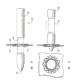
Figure 1 shows that the front view when woven tube of wire is launched, wherein the outer shroud of braided tube or end have been out of shape and have been turned into the petal of holding chamber wall to lumping together, and the front and back petal of unfolded stapling apparatus is represented with pitch black line and light gray line respectively.
Fig. 2 is the side view of braided tube before slipping over the intubate of transporter.
Fig. 3 A is the front view with the similar braided tube of Fig. 1, but has deleted the chamber wall part.
Fig. 3 B is depicted as the side view of braided tube among Fig. 3 A.
Fig. 4 A illustrates transporter that braided tube is housed and the sleeve pipe that is pushed to the transporter end along braided tube.
Fig. 4 B illustrates and inserts the transporter that arrives predetermined piercing site in the body cavity, and the tip wiry that originally is contracted in the intubate further is shown penetrates two chamber walls.
Fig. 4 C illustrates the transporter end of passing two chamber walls, and its sleeve portion withdrawal is to expose the braided tube of sliding on intubate.
Fig. 4 D illustrates and is positioned at the tissue braided tube of the junction of puncturing hole relatively, by the transporter guiding two chamber walls is held in a predetermined position.
The end that Fig. 4 E illustrates braided tube begins to form the unfolded starting stage of braided tube when petal.
Fig. 4 F illustrates braided tube and is in the expansion of clamping two chamber walls, the form that flattens.
Fig. 4 G illustrates the transporter of withdrawing by the opening in the braided tube that flattens in body cavity, left side figure is the end-view of unfolded braided tube among Fig. 4 G, and its state is identical with Fig. 1.
The specific embodiment
Braided tube 10 is determined by quantity, pipe range and the mid diameter of wire diameter, circle and longitudinal opening or diamond 20.The braided tube of elongation is the opening at end place or diamond 20 ' the be meant petal (referring to Fig. 1) when this device is in expansion shape vertically.
In use, force braided tube to form elongated shape (diameter is much smaller than the diameter shown in Fig. 2), and pass the opening placement between the wall tissue in two chambeies, make it return to the shape that flattens among Fig. 1 then.In this process, the tissue of two chamber walls is compressed between the petal of the pipe that flattens (referring to Fig. 1), and the center bore 12 of the pipe that flattens has formed an opening between two chambeies.
For example, braided tube can be applicable to pass ductus choledochus, and can be pushed into and penetrate, and makes it that bile duct is connected to jejunum.This connects after the foundation, can make braided tube distortion, upset that its end is launched as petal, forms the connection between two pipelines.Because this braided tube is made with metal gauze, around the pipe that flattens, will grow scar tissue, final formation forever connects.
Braided tube is made with shape memory metal.Shape memory metal is to change its plasticity when being heated, allow it to change a kind of alloy of shape.If shape memory metal is with required form (with vertical compression shape) annealing, if under the temperature that significantly is lower than annealing temperature to its reheat, after its reshaping (with the cylindrical tube shape), it will revert to its annealed shape (shape that flattens) so.Heat memory this very special nature in low section and flexible transfer system design, be very helpful.The preferred shape memory metal is a Ti-Ni alloy, most preferably is called the nearly Ti-Ni alloy that waits particle of Nitinol.Also having the special nitinol of super elastic characteristics can be in reshaping under the body temperature.
An embodiment of transporter 22 of the present invention comprises that one is contained on the intubate or is contained in braided tube 10 on the driven rod 24 that is covered by the telescopic sleeve pipe shown in Fig. 4 A 26.In an intestinal opposite side coincide application, for example, transporter 22 is inserted in the body cavity by the trocar or pipe (not shown), the end 30 of transporter 22 places the predetermined piercing site of first intestinal segment 28, this intestinal segment 28 can be positioned at the nearside or the distally of required anastomotic position, and transporter 22 is advanced into anastomotic part at intracavity then.
Second intestinal segment 32 is close together at the anastomotic part and first intestinal segment, originally is retracted in the intracavity that intubate 24 intermediary tinsels 34 sharp tips penetrate the intestinal wall of the intestinal wall of first intestinal segment 28 and second intestinal segment 32 and enter second intestinal segment, shown in Fig. 4 B.Sleeve pipe 26 withdrawals, braided tube 10 is pressed Fig. 4 C, 4D, 4E and 4F sequential deployment at the place, junction surface in two coordination holes that produced by tinsel 34 tips, and makes petal design keep two parts intestinal to lumping together at this place.See through the unfolded braided tube of two-layer intestinal shown in Fig. 4 F and 4G.The opposite petal 20 on two-layer intestinal 28 and 32 relative both sides is preferably interlaced, shown in Fig. 1,3A and figure B and 4G.
The foregoing description of the preferred embodiment of the present invention is the purpose that illustrates for example and describe.It is not exhaustive or the present invention is limited to disclosed clear and definite form.Can carry out conspicuous modification or variation by the enlightenment that above-mentioned instruction provides.Selecting and describing present embodiment is for better explanation principle and practical application thereof of the present invention, makes those of ordinary skills use the present invention and the various change that is suitable for special applications is provided with various different embodiment thus.Be endowed the scope of right according to its justice, legal and equality, all such modifications and changing all in determined scope of the present invention by additional claims.
Claims (5)
1. connection chamber or hollow viscus and at the unfolded stapling apparatus in contact surface place, the chamber of two adjacent chambers, comprise a woven tube of wire with vertical alternate end, this braided tube has the design of the metal gauze of crossover, and have unobstructed inside and outside, but this braided tube extending longitudinally makes the elongated diameter of braided tube length diminish, this braided tube is made by hot marmem, has circumferential alternate outer shroud at each place, vertical alternate end of woven tube of wire, thereby after in being inserted into two adjacent chambers cinclides, the braided tube expansion of being heated, diameter becomes big and vertically shrinks, and then axial compression and flattening, the outer annular strain of braided tube also turns up, the thermal deformation upon deployment of the ring of braided tube and the directly opposite one another or interlaced petal of formation that turns up, the petal compression also keeps two adjacent chambers walls to lumping together, the outside and the inside of woven tube of wire keep clear simultaneously, apply enough big power to two adjacent chambers walls, hole between two adjacent chambers is enlarged being used for discharge, and prevent leakage to two adjacent chambers outsides by unfolded tinsel establishment pipe.
2. device according to claim 1, wherein said hot marmem is a Ti-Ni alloy.
3. device according to claim 1, wherein relative petal is interlaced.
4. identical transporter with streamlined end, comprise woven tube of wire with vertical alternate end, this braided tube has the design of the metal gauze of crossover, and having unobstructed inside and outsidely, braided tube has the circumferential alternate outer shroud at each place, vertical alternate end of woven tube of wire; Intubate with end, this cannula design become to allow braided tube to slide and longitudinal stretching on intubate, thereby the elongated diameter of braided tube length is diminished; An outer sleeve, this sleeve pipe be suitable for being covered on this braided tube and on be pushed into the streamlined end of this device, thereby provide a smooth surface that is used to insert the two adjacent body lumen wall of passing body cavity contact surface place, and withdrawal subsequently; The tinsel that the tip is arranged, be retracted in the intubate when it begins, and be suitable for exposing its tip in two adjacent chambers walls, to produce the hole, thereby this device is being passed chamber wall help surgeon, this braided tube is made by hot marmem, thereby when cannula retraction, diameter became big and vertically contraction when body temperature launched braided tube, and then become axial compression and flatten, cause the outer annular strain of braided tube and turn up, form staggered each other petal, the petal compression also keeps two adjacent chambers walls to lumping together, and the outside and the inside of woven tube of wire keep clear simultaneously, apply enough big power to two adjacent chambers walls, hole between two adjacent chambers is enlarged being used for discharge, and prevent leakage independently to two adjacent chambers outsides by unfolded woven tube of wire.
5. device according to claim 4, wherein hot marmem is a Ti-Ni alloy.
Applications Claiming Priority (2)
| Application Number | Priority Date | Filing Date | Title |
|---|---|---|---|
| US29961801P | 2001-06-20 | 2001-06-20 | |
| US60/299,618 | 2001-06-20 |
Publications (2)
| Publication Number | Publication Date |
|---|---|
| CN1531411A CN1531411A (en) | 2004-09-22 |
| CN100415180C true CN100415180C (en) | 2008-09-03 |
Family
ID=23155556
Family Applications (1)
| Application Number | Title | Priority Date | Filing Date |
|---|---|---|---|
| CNB028122755A Expired - Fee Related CN100415180C (en) | 2001-06-20 | 2002-06-20 | Anastomotic device |
Country Status (11)
| Country | Link |
|---|---|
| US (1) | US20030032967A1 (en) |
| EP (1) | EP1401337B1 (en) |
| JP (1) | JP4201702B2 (en) |
| KR (1) | KR100891045B1 (en) |
| CN (1) | CN100415180C (en) |
| AT (1) | ATE512631T1 (en) |
| BR (1) | BR0210509A (en) |
| CA (1) | CA2450959C (en) |
| MX (1) | MXPA03012055A (en) |
| NZ (1) | NZ530597A (en) |
| WO (1) | WO2003000142A2 (en) |
Families Citing this family (67)
| Publication number | Priority date | Publication date | Assignee | Title |
|---|---|---|---|---|
| US7608086B2 (en) * | 2003-09-30 | 2009-10-27 | Ethicon Endo-Surgery, Inc. | Anastomosis wire ring device |
| AU2005203522B2 (en) * | 2003-09-30 | 2012-08-02 | Ethicon Endo-Surgery, Inc. | Applier for a surgical device |
| US8211142B2 (en) * | 2003-09-30 | 2012-07-03 | Ortiz Mark S | Method for hybrid gastro-jejunostomy |
| US20050070935A1 (en) | 2003-09-30 | 2005-03-31 | Ortiz Mark S. | Single lumen access deployable ring for intralumenal anastomosis |
| US7309341B2 (en) * | 2003-09-30 | 2007-12-18 | Ethicon Endo-Surgery, Inc. | Single lumen anastomosis applier for self-deploying fastener |
| US20050070939A1 (en) * | 2003-09-30 | 2005-03-31 | Jean Beaupre | Unfolding anastomosis ring device |
| CA2482697C (en) * | 2003-09-30 | 2012-11-20 | Ethicon Endo-Surgery, Inc. | Applier for a surgical device |
| US7452363B2 (en) * | 2003-09-30 | 2008-11-18 | Ethicon Endo-Surgery, Inc. | Applier for fastener for single lumen access anastomosis |
| US20050085787A1 (en) * | 2003-10-17 | 2005-04-21 | Laufer Michael D. | Minimally invasive gastrointestinal bypass |
| DE102004023527A1 (en) * | 2004-05-13 | 2005-12-08 | Osypka, Peter, Dr.-Ing. | measuring device |
| US7470275B2 (en) * | 2005-05-03 | 2008-12-30 | Ethicon Endo-Surgery, Inc. | Anastomotic ring applier device providing forward and retrograde visualization |
| US7758589B2 (en) * | 2005-05-03 | 2010-07-20 | Ethicon Endo-Surgery, Inc. | Surgical instrument for extracting an anastomotic ring device |
| US7547311B2 (en) * | 2005-05-03 | 2009-06-16 | Ethicon Endo-Surgery, Inc. | Spring-based firing mechanism for anastomotic ring applier |
| US7462186B2 (en) * | 2005-05-03 | 2008-12-09 | Ethicon Endo-Surgery, Inc. | Anastomotic ring applier device utilizing an electroactive polymer |
| US7534247B2 (en) * | 2005-05-03 | 2009-05-19 | Ethicon Endo-Surgery, Inc. | Sheathless anastomotic ring applier device |
| US7632285B2 (en) * | 2005-05-03 | 2009-12-15 | Ethicon Endo-Surgery, Inc. | Sheath for enabling insertion and extraction of anastomotic ring applier |
| US7645287B2 (en) * | 2005-05-03 | 2010-01-12 | Ethicon Endo-Surgery, Inc. | Articulating anastomotic ring applier |
| US7691113B2 (en) * | 2005-05-05 | 2010-04-06 | Ethicon Endo-Surgery, Inc. | Screw tip control for anastomotic ring applier |
| US7645288B2 (en) * | 2005-05-05 | 2010-01-12 | Ethicon Endo-Surgery, Inc. | Anastomotic ring applier with inflatable members |
| US7445622B2 (en) * | 2005-05-05 | 2008-11-04 | Ethicon Endo-Surgery, Inc. | Anastomotic ring applier with double motion actuation |
| US7591828B2 (en) * | 2005-07-22 | 2009-09-22 | Ethicon Endo-Surgery, Inc. | Resposable anastomotic ring applier device |
| US20070021758A1 (en) * | 2005-07-22 | 2007-01-25 | Ethicon Endo-Surgery, Inc. | Anastomotic ring applier for use in colorectal applications |
| US20070021759A1 (en) | 2005-07-22 | 2007-01-25 | Ethicon Endo-Surgery, Inc. | Flexible endoscopic anastomotic ring applier device |
| US8029522B2 (en) * | 2005-08-05 | 2011-10-04 | Ethicon Endo-Surgery, Inc. | Method and apparatus for sealing a gastric opening |
| US7798992B2 (en) * | 2005-11-04 | 2010-09-21 | Ethicon Endo-Surgery, Inc. | Lumen traversing device |
| US7651017B2 (en) | 2005-11-23 | 2010-01-26 | Ethicon Endo-Surgery, Inc. | Surgical stapler with a bendable end effector |
| US20070123917A1 (en) * | 2005-11-29 | 2007-05-31 | Ortiz Mark S | Anastomotic device promoting tissue necrosis |
| US8221438B2 (en) * | 2006-02-17 | 2012-07-17 | Ethicon Endo-Surgery, Inc. | Lumen reduction methods and devices |
| US20070198032A1 (en) * | 2006-02-22 | 2007-08-23 | Ethicon Endo-Surgery, Inc. | Methods and devices for fastener removal |
| US8376981B2 (en) * | 2006-03-02 | 2013-02-19 | Michael D. Laufer | Gastrointestinal implant and methods for use |
| WO2007103773A2 (en) * | 2006-03-02 | 2007-09-13 | Laufer Michael D | Gastrointestinal implant and methods for use |
| US20070225556A1 (en) * | 2006-03-23 | 2007-09-27 | Ethicon Endo-Surgery, Inc. | Disposable endoscope devices |
| US7615004B2 (en) | 2006-03-30 | 2009-11-10 | Ethicon Endo-Surgery, Inc. | Endoscopic ancillary attachment devices |
| US20070239179A1 (en) * | 2006-03-31 | 2007-10-11 | Ethicon Endo-Surgery, Inc. | Compliant Gastroplasty: Devices And Methods |
| US20070276409A1 (en) * | 2006-05-25 | 2007-11-29 | Ethicon Endo-Surgery, Inc. | Endoscopic gastric restriction methods and devices |
| US7635373B2 (en) * | 2006-05-25 | 2009-12-22 | Ethicon Endo-Surgery, Inc. | Absorbable gastric restriction devices and methods |
| US8603138B2 (en) * | 2006-10-04 | 2013-12-10 | Ethicon Endo-Surgery, Inc. | Use of an adhesive to treat intraluminal bleeding |
| US7914511B2 (en) * | 2006-10-18 | 2011-03-29 | Ethicon Endo-Surgery, Inc. | Use of biosurgical adhesive as bulking agent |
| US8876844B2 (en) * | 2006-11-01 | 2014-11-04 | Ethicon Endo-Surgery, Inc. | Anastomosis reinforcement using biosurgical adhesive and device |
| WO2008055301A1 (en) | 2006-11-07 | 2008-05-15 | Univ Sydney | Devices and methods for the treatment of heart failure |
| US10413284B2 (en) | 2006-11-07 | 2019-09-17 | Corvia Medical, Inc. | Atrial pressure regulation with control, sensing, monitoring and therapy delivery |
| US9232997B2 (en) | 2006-11-07 | 2016-01-12 | Corvia Medical, Inc. | Devices and methods for retrievable intra-atrial implants |
| US20110257723A1 (en) | 2006-11-07 | 2011-10-20 | Dc Devices, Inc. | Devices and methods for coronary sinus pressure relief |
| US8465515B2 (en) * | 2007-08-29 | 2013-06-18 | Ethicon Endo-Surgery, Inc. | Tissue retractors |
| US8128559B2 (en) | 2007-11-26 | 2012-03-06 | Ethicon Endo-Surgery, Inc. | Tissue retractors |
| US8517931B2 (en) * | 2007-11-26 | 2013-08-27 | Ethicon Endo-Surgery, Inc. | Tissue retractors |
| CN102905626A (en) | 2010-01-29 | 2013-01-30 | Dc设备公司 | Devices and systems for treating heart failure |
| CN103118607B (en) * | 2010-07-16 | 2015-09-23 | 伊西康内外科公司 | Bile is guided to the device of enteral from gallbladder |
| WO2012007052A1 (en) | 2010-07-16 | 2012-01-19 | Ethicon Endo-Surgery, Inc. | A device for an endoluminal cholecysto - enterostomy |
| WO2012007042A1 (en) | 2010-07-16 | 2012-01-19 | Ethicon Endo-Surgery, Inc. | An anastomosis device for a cholecysto-enterostomy |
| US9463269B2 (en) | 2010-09-10 | 2016-10-11 | W. L. Gore & Associates, Inc. | Anastomotic devices and methods |
| US8535259B2 (en) | 2010-12-29 | 2013-09-17 | Ethicon Endo-Surgery, Inc. | Methods for biliary diversion |
| CN107334512B (en) | 2011-02-10 | 2021-04-13 | 可维亚媒体公司 | Device for creating and maintaining an intra-atrial pressure relief opening |
| BR112013022861A2 (en) | 2011-03-08 | 2016-12-06 | Gore & Ass | medical device for use with a stoma |
| FR2976782B1 (en) | 2011-06-22 | 2014-05-09 | Cousin Biotech | ANASTOMOTIC DEVICE AND METHOD FOR MANUFACTURING SUCH A DEVICE. |
| US9205236B2 (en) | 2011-12-22 | 2015-12-08 | Corvia Medical, Inc. | Methods, systems, and devices for resizable intra-atrial shunts |
| FR3009185A1 (en) | 2013-08-01 | 2015-02-06 | Cousin Biotech | ANASTOMOTIC DEVICE FOR JOINING LUMENS OR VISCERES BETWEEN THEM |
| US10675450B2 (en) | 2014-03-12 | 2020-06-09 | Corvia Medical, Inc. | Devices and methods for treating heart failure |
| US9554801B2 (en) | 2014-03-14 | 2017-01-31 | Cook Medical Technologies Llc | Extravascular implant for facilitating sutured side-to-side arteriovenous fistula creation and maintaining patency |
| US9993251B2 (en) | 2014-05-02 | 2018-06-12 | W. L. Gore & Associates, Inc. | Anastomosis devices |
| US11712230B2 (en) | 2014-05-02 | 2023-08-01 | W. L. Gore & Associates, Inc. | Occluder and anastomosis devices |
| JP6799526B2 (en) | 2014-07-23 | 2020-12-16 | コルヴィア メディカル インコーポレイテッド | Equipment and methods for the treatment of heart failure |
| US11724075B2 (en) | 2017-04-18 | 2023-08-15 | W. L. Gore & Associates, Inc. | Deployment constraining sheath that enables staged deployment by device section |
| KR101976743B1 (en) * | 2017-07-14 | 2019-05-09 | 주식회사 비씨엠 | Stent insertion device for human digestive organ connection |
| EP4238539A3 (en) | 2017-10-25 | 2023-10-18 | Boston Scientific Scimed, Inc. | Stent with atraumatic spacer |
| WO2019089741A1 (en) | 2017-11-01 | 2019-05-09 | Boston Scientific Scimed, Inc. | Esophageal stent including a valve member |
| WO2021081360A1 (en) * | 2019-10-24 | 2021-04-29 | Atrium Medical Corporation | Endovascular fixation device |
Citations (4)
| Publication number | Priority date | Publication date | Assignee | Title |
|---|---|---|---|---|
| US5540712A (en) * | 1992-05-01 | 1996-07-30 | Nitinol Medical Technologies, Inc. | Stent and method and apparatus for forming and delivering the same |
| US6007544A (en) * | 1996-06-14 | 1999-12-28 | Beth Israel Deaconess Medical Center | Catheter apparatus having an improved shape-memory alloy cuff and inflatable on-demand balloon for creating a bypass graft in-vivo |
| CN2394583Y (en) * | 1999-06-05 | 2000-09-06 | 彭罗民 | Medical blood vessel anastomat |
| US6321587B1 (en) * | 1999-10-15 | 2001-11-27 | Radian International Llc | Solid state fluorine sensor system and method |
Family Cites Families (34)
| Publication number | Priority date | Publication date | Assignee | Title |
|---|---|---|---|---|
| SE445884B (en) * | 1982-04-30 | 1986-07-28 | Medinvent Sa | DEVICE FOR IMPLANTATION OF A RODFORM PROTECTION |
| US5067957A (en) * | 1983-10-14 | 1991-11-26 | Raychem Corporation | Method of inserting medical devices incorporating SIM alloy elements |
| US4665906A (en) * | 1983-10-14 | 1987-05-19 | Raychem Corporation | Medical devices incorporating sim alloy elements |
| US4733665C2 (en) * | 1985-11-07 | 2002-01-29 | Expandable Grafts Partnership | Expandable intraluminal graft and method and apparatus for implanting an expandable intraluminal graft |
| US5197978B1 (en) * | 1991-04-26 | 1996-05-28 | Advanced Coronary Tech | Removable heat-recoverable tissue supporting device |
| US5876445A (en) * | 1991-10-09 | 1999-03-02 | Boston Scientific Corporation | Medical stents for body lumens exhibiting peristaltic motion |
| US5720776A (en) * | 1991-10-25 | 1998-02-24 | Cook Incorporated | Barb and expandable transluminal graft prosthesis for repair of aneurysm |
| US5376376A (en) * | 1992-01-13 | 1994-12-27 | Li; Shu-Tung | Resorbable vascular wound dressings |
| ES2133382T3 (en) * | 1992-01-21 | 1999-09-16 | Univ Minnesota | DEVICE FOR THE CLOSURE OF SEPTAL DEFECTS. |
| RU2089131C1 (en) * | 1993-12-28 | 1997-09-10 | Сергей Апполонович Пульнев | Stent-expander |
| US5466242A (en) * | 1994-02-02 | 1995-11-14 | Mori; Katsushi | Stent for biliary, urinary or vascular system |
| US6123715A (en) * | 1994-07-08 | 2000-09-26 | Amplatz; Curtis | Method of forming medical devices; intravascular occlusion devices |
| US5846261A (en) * | 1994-07-08 | 1998-12-08 | Aga Medical Corp. | Percutaneous catheter directed occlusion devices |
| US5725552A (en) * | 1994-07-08 | 1998-03-10 | Aga Medical Corporation | Percutaneous catheter directed intravascular occlusion devices |
| US5575818A (en) * | 1995-02-14 | 1996-11-19 | Corvita Corporation | Endovascular stent with locking ring |
| DE19508805C2 (en) * | 1995-03-06 | 2000-03-30 | Lutz Freitag | Stent for placement in a body tube with a flexible support structure made of at least two wires with different shape memory functions |
| BE1009278A3 (en) * | 1995-04-12 | 1997-01-07 | Corvita Europ | Guardian self-expandable medical device introduced in cavite body, and medical device with a stake as. |
| ATE515237T1 (en) * | 1995-10-13 | 2011-07-15 | Medtronic Vascular Inc | DEVICE AND SYSTEM FOR AN INTERSTITIAL TRANSVASCULAR PROCEDURE |
| WO1997013463A1 (en) * | 1995-10-13 | 1997-04-17 | Transvascular, Inc. | Methods and apparatus for bypassing arterial obstructions and/or performing other transvascular procedures |
| US6348066B1 (en) * | 1995-11-07 | 2002-02-19 | Corvita Corporation | Modular endoluminal stent-grafts and methods for their use |
| CN1218414A (en) * | 1996-02-02 | 1999-06-02 | 血管转换公司 | Methods and apparatus for blocking flow through blood vessels |
| US5676670A (en) * | 1996-06-14 | 1997-10-14 | Beth Israel Deaconess Medical Center | Catheter apparatus and method for creating a vascular bypass in-vivo |
| US5797920A (en) * | 1996-06-14 | 1998-08-25 | Beth Israel Deaconess Medical Center | Catheter apparatus and method using a shape-memory alloy cuff for creating a bypass graft in-vivo |
| US5741297A (en) * | 1996-08-28 | 1998-04-21 | Simon; Morris | Daisy occluder and method for septal defect repair |
| IL121316A (en) * | 1997-07-15 | 2001-07-24 | Litana Ltd | Implantable medical device of shape memory alloy |
| US6193734B1 (en) * | 1998-01-23 | 2001-02-27 | Heartport, Inc. | System for performing vascular anastomoses |
| EP1685808B1 (en) * | 1998-01-30 | 2016-09-14 | St.Jude Medical ATG, Inc. | Device for use in closing septal defects and an installation assembly for such device |
| US5938697A (en) * | 1998-03-04 | 1999-08-17 | Scimed Life Systems, Inc. | Stent having variable properties |
| US6206913B1 (en) * | 1998-08-12 | 2001-03-27 | Vascular Innovations, Inc. | Method and system for attaching a graft to a blood vessel |
| US6152937A (en) * | 1998-11-06 | 2000-11-28 | St. Jude Medical Cardiovascular Group, Inc. | Medical graft connector and methods of making and installing same |
| US6113612A (en) * | 1998-11-06 | 2000-09-05 | St. Jude Medical Cardiovascular Group, Inc. | Medical anastomosis apparatus |
| US6165185A (en) * | 1999-07-28 | 2000-12-26 | Vasconnect, Inc. | Method for interconnecting vessels in a patient |
| SE515231C2 (en) * | 1999-10-13 | 2001-07-02 | Jan Otto Solem | Covered stent and way to manufacture the same |
| US7115136B2 (en) * | 2001-06-20 | 2006-10-03 | Park Medical Llc | Anastomotic device |
-
2002
- 2002-06-20 BR BR0210509-8A patent/BR0210509A/en not_active Application Discontinuation
- 2002-06-20 WO PCT/US2002/019566 patent/WO2003000142A2/en active Application Filing
- 2002-06-20 MX MXPA03012055A patent/MXPA03012055A/en active IP Right Grant
- 2002-06-20 JP JP2003506593A patent/JP4201702B2/en not_active Expired - Fee Related
- 2002-06-20 EP EP02749617A patent/EP1401337B1/en not_active Expired - Lifetime
- 2002-06-20 CN CNB028122755A patent/CN100415180C/en not_active Expired - Fee Related
- 2002-06-20 NZ NZ530597A patent/NZ530597A/en not_active IP Right Cessation
- 2002-06-20 KR KR1020037016609A patent/KR100891045B1/en not_active IP Right Cessation
- 2002-06-20 AT AT02749617T patent/ATE512631T1/en not_active IP Right Cessation
- 2002-06-20 CA CA2450959A patent/CA2450959C/en not_active Expired - Lifetime
- 2002-06-20 US US10/175,159 patent/US20030032967A1/en not_active Abandoned
Patent Citations (4)
| Publication number | Priority date | Publication date | Assignee | Title |
|---|---|---|---|---|
| US5540712A (en) * | 1992-05-01 | 1996-07-30 | Nitinol Medical Technologies, Inc. | Stent and method and apparatus for forming and delivering the same |
| US6007544A (en) * | 1996-06-14 | 1999-12-28 | Beth Israel Deaconess Medical Center | Catheter apparatus having an improved shape-memory alloy cuff and inflatable on-demand balloon for creating a bypass graft in-vivo |
| CN2394583Y (en) * | 1999-06-05 | 2000-09-06 | 彭罗民 | Medical blood vessel anastomat |
| US6321587B1 (en) * | 1999-10-15 | 2001-11-27 | Radian International Llc | Solid state fluorine sensor system and method |
Also Published As
| Publication number | Publication date |
|---|---|
| JP4201702B2 (en) | 2008-12-24 |
| MXPA03012055A (en) | 2005-07-01 |
| KR100891045B1 (en) | 2009-03-31 |
| JP2004535864A (en) | 2004-12-02 |
| EP1401337A2 (en) | 2004-03-31 |
| CN1531411A (en) | 2004-09-22 |
| ATE512631T1 (en) | 2011-07-15 |
| US20030032967A1 (en) | 2003-02-13 |
| EP1401337B1 (en) | 2011-06-15 |
| KR20040024563A (en) | 2004-03-20 |
| WO2003000142B1 (en) | 2003-05-08 |
| WO2003000142A2 (en) | 2003-01-03 |
| CA2450959A1 (en) | 2003-01-03 |
| BR0210509A (en) | 2004-06-22 |
| CA2450959C (en) | 2011-01-04 |
| NZ530597A (en) | 2006-10-27 |
| WO2003000142A3 (en) | 2003-03-27 |
Similar Documents
| Publication | Publication Date | Title |
|---|---|---|
| CN100415180C (en) | Anastomotic device | |
| US7780686B2 (en) | Anastomotic device | |
| US20210378672A1 (en) | Tissue anchor for securing tissue layers | |
| US5941908A (en) | Artificial medical graft with a releasable retainer | |
| US5540713A (en) | Apparatus for widening a stenosis in a body cavity | |
| AU2017203884B2 (en) | Devices and methods for forming an anastomosis | |
| US8454632B2 (en) | Tissue anchor for securing tissue layers | |
| CN102202607A (en) | Introducer for deploying a stent graft in a curved lumen | |
| JP2001519698A (en) | Endovascular graft for treatment of abdominal aortic aneurysm | |
| JP2002526176A (en) | Guidewire capture device | |
| US20080294235A1 (en) | Bypass graft device and delivery system and method | |
| CN210903227U (en) | Hepatobiliary surgery stone extractor | |
| AU2002320117B2 (en) | Anastomotic device | |
| AU2002320117A1 (en) | Anastomotic device | |
| EP4079234A1 (en) | Apparatus for forming an anastomosis | |
| WO2021081360A1 (en) | Endovascular fixation device |
Legal Events
| Date | Code | Title | Description |
|---|---|---|---|
| C06 | Publication | ||
| PB01 | Publication | ||
| C10 | Entry into substantive examination | ||
| SE01 | Entry into force of request for substantive examination | ||
| C14 | Grant of patent or utility model | ||
| GR01 | Patent grant | ||
| CF01 | Termination of patent right due to non-payment of annual fee |
Granted publication date: 20080903 Termination date: 20170620 |
|
| CF01 | Termination of patent right due to non-payment of annual fee |